PDF p. 1655 · 4-45
- 1.Remove the related parts.
- Rear seat.
- Trim and other luggage compartment fittings.
- Left and right rear suspension assembly.
- Parking brake parts.
- Muffler.
- Wire harness.
- Other parts as necessary.
- Propeller shaft, rear differential and related parts (4WD)
- Fuel tank and fuel lines.
- 2.4WD: Remove the rear differential mounting bracket A, rear differential mounting rubber and rear differential mounting bracket B.
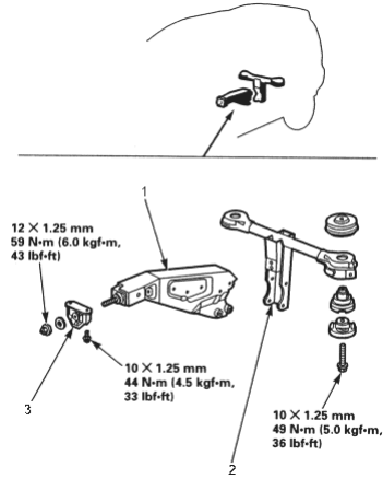
- 1. REAR DIFFERENTIAL MOUNTING BRACKET A
- 2. REAR DIFFERENTIAL MOUNTING BRACKET B
- 3. REAR DIFFERENTIAL MOUNTING RUBBER
- 3.Pull out and straighten the damage area.
- Check whether the damage extended to the rear floor cross-member, rear wheelhouse, and the passenger compartment. Pull out the damaged parts using the frame corrector.
- Impact damage to the rear floor spreads to related parts such as the rear frame, rear floor cross-member and rear wheelhouse.
- Therefore, pull out the damaged areas with the frame straightener and measure in reference to body dimensional drawing.
NOTE: Use of a positioning jig is recommended (see page 1-7).
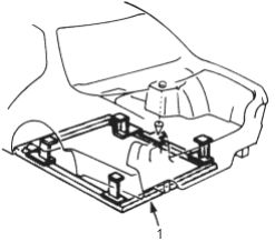
- 1. POSITIONING JIG
- 4.Peel off the undercoat. Heat the undercoat at the weld areas of the lower rear floor with a gas torch and peel off the undercoat with a metal spatula.
- 5.Cut and pry off the rear panel (see page 4-41).
PDF p. 1656 · 4-46
- 6.Cut and pry off the rear floor.
- Cut off the rear floor with a gas cutter or air chisel.
- Leave the spot welded flanges of the rear frame and rear floor cross-member.
NOTE:
- Cut the rear floor 15 mm (0.6 in.) from the welded flange of the rear floor cross-member.
- Do not drill down to the rear frame.
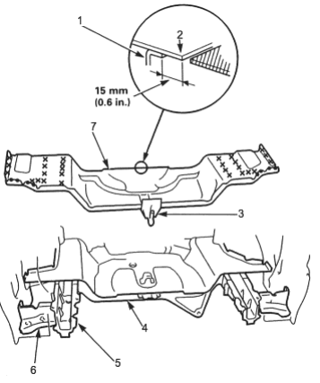
- 1. REAR FLOOR CROSS-MEMBER
- 2. REAR FLOOR
- 3. TIE DOWN STIFFENER
- 4. REAR FLOOR CROSS-MEMBER
- 5. REAR FRAME C
- 6. REAR FRAME GUSSET
- 7. REAR FLOOR
- Centre punch around the spot weld imprints on the remaining welded flanges.
- Drill holes with a spot cutter.
- 7.Check the damage and position of the rear frame and rear floor cross-member.
- Smooth the welding flanges of the rear frame with a hammer and dolly.
NOTE: Check that the rear frame is parallel at the right and left.
- 8.
If necessary, cut the rear frame C and rear floor cross-member.
NOTE: Replace the rear frame and gusset and rear frame C as an assembly.
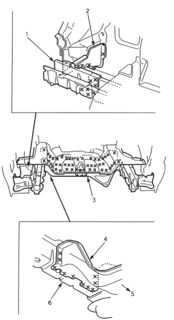
- 1. REAR FRAME C
- 2. REAR FRAME END GUSSET
- 3. REAR FLOOR CROSS-MEMBER
- 4. REAR FLOOR CROSS-MEMBER
- 5. Forward
- 6. REAR FRAME B
- Strike a centre punch around the spot weld imprints on the rear floor cross-member from inside the trunk compartment.
- Drill out the spot welds with the spot cutter.
NOTE: Keep the holes to a minimum since they will be used as weld holes MIG welding of the new part.
PDF p. 1657 · 4-47
- 9.Straighten the related parts.
- Remove the burrs from the spot weld or MIG weld using a sander.
- Fill any holes made in the spot welded areas of the flange by MIG or gas welding.
- 10.
Keep the body level.
Jack the body at the front and back. Place safety stands at the four designated places of the side sill.
- 11.Set the new rear floor cross-member and rear frame C and check the position of the rear frames using the body dimensional drawings (see section 6) and the positioning jig.
- 12.Tack weld the new rear floor cross-member and rear frame C.
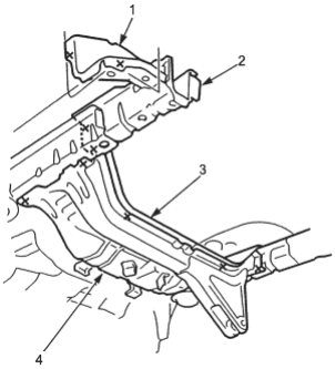
- 1. REAR FRAME END GUSSET
- 2. REAR FRAME C
- 3. REAR FLOOR
- 4. REAR FLOOR CROSS-MEMBER
- 13.
Cut the new rear floor to align it with the body.
NOTE:
- Cut the new part so it overlaps the body side floor by approximately 40 mm (1.6 in.)
- Do not cut the tie down stiffener.
- Insert the tie down stiffener of the new rear floor between the body side rear floor and rear floor cross-member.
Remove the undercoat from both sides of the areas to be welded with a sander to expose the steel plate.
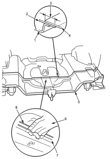
- 1. REAR FLOOR CROSS-MEMBER
- 2. REAR FLOOR (Body side)
- 3. Overlap 40 mm (1.6 in.)
- 4. REAR FLOOR (New part)
- 5. REAR FLOOR (New part)
- 6. TIE DOWN STIFFENER
- 7. REAR FLOOR CROSS-MEMBER
- 8. REAR FLOOR (Body side)
- 14.Clamp the new rear floor and check the position of the rear wheelhouse, inner panel and outer panel.
- 15.Remove the new rear floor.
PDF p. 1658 · 4-48
- 16.Weld the rear floor cross-member and rear floor (body side) and weld the rear frame C and rear frame end gusset.
NOTE: Weld as much as possible with the positioning jig still mounted.
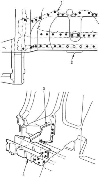
- 1. REAR FLOOR CROSS-MEMBER
- 2. Do not weld the welding portion of the tie down stiffener
- 3. REAR FRAME END GUSSET
- 4. REAR FRAME C
- 17.
Finish the welding area.
Roughly grind the welds in the trunk compartment with a disc grinder. Be sure to leave the finishing allowance.
NOTE: Take care not to grind excessively.
- 18.Set the new rear floor.
- Drill the holes for welding the new rear floor.
- Check that the weld flange surfaces fit closely.
- Tack weld the new rear floor.
- 19.Clamp the rear panel and check the outer panel and rear pillar gutter position.
- 20.Main weld the new rear floor, rear frame C and rear floor cross-member.
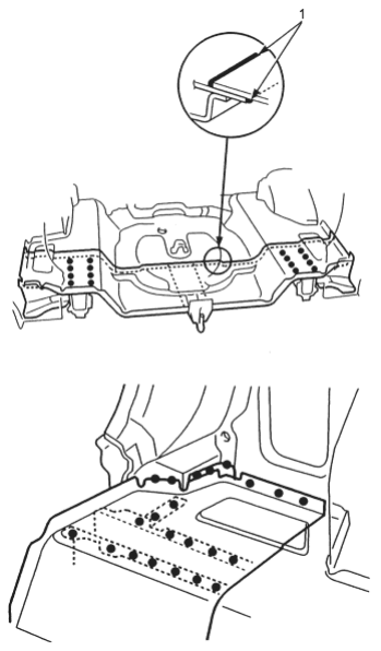
- 1. Fillet welding
PDF p. 1659 · 4-49
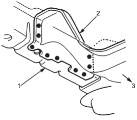
- 1. REAR FRAME B
- 2. REAR FLOOR CROSS-MEMBER
- 3. Forward
Drill the holes for welding the tie down stiffener from under the rear floor and weld the rear floor, tie
down stiffener and rear floor cross-member with a MIG welder.
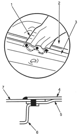
- 1. TIE DOWN STIFFENER
- 2. REAR FLOOR (Body side)
- 3. REAR FLOOR CROSS-MEMBER
- 4. REAR FLOOR (New part)
- 5. TIE DOWN STIFFENER
- 6. REAR FLOOR CROSS-MEMBER
- 7. REAR FLOOR (Body side)
- 21.Weld the rear panel (see page 4-21).
- 22.
Finish the welded area.
Even out the welded area with a hammer and dolly and fit the flange surfaces closely together.
- 23.Apply sealer at the overlapped area of the rear floor, and the welded surfaces of the rear wheelhouse and rear end inner panel. Seal gaps completely (see section 5).
- 24.Apply the paint. See Pant Repair section.
- 25.
Apply the undercoat.
Apply anti-rust agent to the inside of the rear floor cross-member, tie down stiffener, and jointed areas of the rear floor (see section 7).
- 26.Weld the rear panel and install the related parts. Install in the reverse order in which they were removed.
- 27.Inspect and clean.
- Measure the rear wheel alignment.
- Clean the inside of the trunk compartment.