PDF p. 936 · 19-B-32
- 1.Check the front and rear pulser for chipped or damaged teeth.
- 2.
Measure the air gap between the wheel sensor and pulser all the way around while rotating the pulser. If the air gap exceeds 1.0 mm (0.04 in), check for a bent suspension arm.
Standard:
Front/Rear: 0.4-1.2 mm (0.02-0.05 in) Front/Rear
Remove the rear brake drum to inspect the rear wheel sensor air gap.
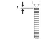
- 1. 0.4-1.2 mm (0.02-0.05 in)
Wheel Sensor Replacement
Install the sensors carefully to avoid twisting the wires.
Front
When installing the front wheel sensor, pass the sensor through between the knuckle and the brake hose.
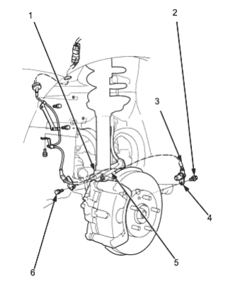
- 1. KNUCKLE
- 2. 8 mm BOLT, 22 Nm (2.2 kgf/m, 16 lbf/ft)
- 3. SENSOR WIRE
- 4. WHEEL SENSOR
- 5. BRAKE HOSE
- 6. 6 mm BOLT, 9.8 Nm (1.0 kgf/m, 7.2 lbf/ft)
Rear
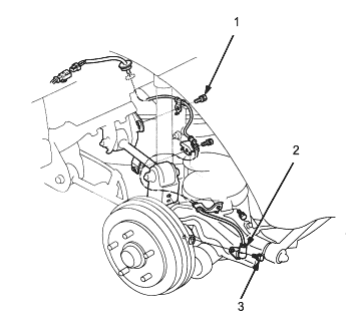
- 1. 6 mm BOLT, 9.8 Nm (1.0 kgf/m, 7.2 lbf/ft)
- 2. WHEEL SENSOR
- 3. 8 mm BOLT, 22 Nm (2.2 kgf/m, 16 lbf/ft)