PDF p. 935 · 19-B-31
Note:
- Do not spill brake fluid on the vehicle; it may damage the paint; if brake fluid does contact the paint, wash it off immediately with water.
- Take care not to damage or deform the brake lines during removal and installation.
- To prevent the brake fluid from flowing, plug and cover the hose ends and joints with a shop towel or equivalent material.
Removal
- 1.Disconnect the ABS control unit connector as described below.
- 1.Pull the connector lock.
- 2.Disconnect the connector.
- 1.
- 2.Disconnect the brake pipes, then remove the modulator assembly.
Installation
- 1.Install the modulator assembly, then connect the brake pipes.
- 2.Connect the ABS control unit connector in the reverse order of disconnection.
- 3.Bleed the brake system, starting with the front wheels.
- 4.Start the engine, and check that the ABS indicator goes off.
- 5.Test-drive the vehicle, and check that the ABS indicator does not come on.
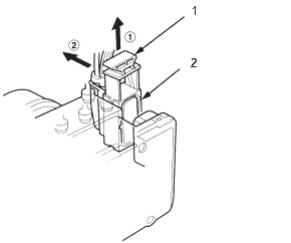
- 1. CONNECTOR LOCK
- 2. ABS CONTROL UNIT CONNECTOR
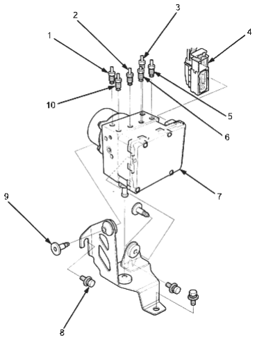
- 1. To master cylinder secondary side
- 2. To right-rear wheel cylinder
- 3. To master cylinder primary side
- 4. ABS CONTROL UNIT CONNECTOR
- 5. To right-front caliper
- 6. To left-rear wheel cylinder
- 7. MODULATOR ASSEMBLY (ABS CONTROL UNIT/MODULATOR UNIT)
- 8. 8 mm BOLT
22 Nm (2.2 kgf/m, 16 lbf/ft) - 9. TORX BOLT
9.8 Nm (1.0 kgf/m, 7.2 lbf/ft) - 10. To left-front caliper