PDF p. 916 · 19-B-12
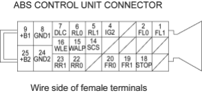
| Terminal | Wire colour | Terminal sign | Description | Measurement | |||
|---|---|---|---|---|---|---|---|
| No. | (Terminal name) | Terminal | Conditions (Ignition switch ON (II) | Voltage | |||
| 1 | GRN/ORN | FL1 | Detects left-front | 1-2 | Wheel | Turn wheel at | AC: 0.053V or |
| (Front-left 1) | wheel sensor signal | 1 turn/second | above | ||||
| (Reference) | |||||||
| Oscilloscope: | |||||||
| 0.15 Vp-p or | |||||||
| above | |||||||
| 2 | BRN/WHT | FL0 | Detects left-front | 1-2 | Wheel | Turn wheel at | AC: 0.053V or |
| (Front-left 0)) | wheel sensor signal | 1 turn/second | above | ||||
| (Reference) | |||||||
| Oscilloscope: | |||||||
| 0.15 Vp-p or | |||||||
| above | |||||||
| 4 | BLK/YEL | IG2 | Power source for | 4-GND | Battery Voltage | ||
| (Ignition 2) | activating the system | ||||||
| 5 | LT BLU | RL1 | Detects left-rear | 5-6 | Wheel | Turn wheel at | AC: 0.053V or |
| (Rear-left 1) | wheel sensor signal | 1 turn/second | above | ||||
| (Reference) | |||||||
| Oscilloscope: | |||||||
| 0.15 Vp-p or | |||||||
| above | |||||||
| 6 | GRY | RL0 | Detects left-rear | 5-6 | Wheel | Turn wheel at | AC: 0.053V or |
| (Rear-left 0) | wheel sensor signal | 1 turn/second | above | ||||
| (Reference) | |||||||
| Oscilloscope: | |||||||
| 0.15 Vp-p or | |||||||
| above | |||||||
| 7 | LT BLU | DLC | Communicates with | - | - | - | |
| (Data link connector) | the Honda PGM | ||||||
| Tester | |||||||
| 8 | BLK | GND1 | Ground | - | - | - | |
| (Ground 1) | |||||||
| 9 | GRN | +B1 | Power source for the | 9-GND | Every time | Battery Voltage | |
| (Battery 1) | solenoid valve | ||||||
| 14 | BRN | SCS | Detects service | - | - | - | |
| (Service check | check connector | ||||||
| signal) | signal (DTC | ||||||
| indication or DTC | |||||||
| clearing) | |||||||
| 15 | BLU/RED | WALP | Drives ABS indicator | 15-GND | ABS indicator | ON | 4-6 V |
| (Warning lamp) | (Turns the indicator | ||||||
| drive transistor to | |||||||
| ON, then turns off | |||||||
| the indication). | |||||||
| 15 | BLU/RED | WALP | Drives ABS indicator | 15-GND | ABS indicator | OFF | Below 0.3 V*1 |
| (Warning lamp) | (Turns the indicator | ||||||
| drive transistor to | |||||||
| ON, then turns off | |||||||
| the indication). | |||||||
| 16 | GRY/BLK | WLE | Drives brake system | 16-GND | Brake system | ON | Below 0.3 V |
| (Warning lamp EBD) | indicator (Turns the | indicator | |||||
| indicator drive | |||||||
| transistor to OFF, | |||||||
| then turns off the | |||||||
| indicator | |||||||
| 16 | GRY/BLK | WLE | Drives brake system | 16-GND | Brake system | OFF | Battery voltage |
| (Warning lamp EBD | indicator (Turns the | indicator | |||||
| indicator drive | |||||||
| transistor to OFF, | |||||||
| then turns off the | |||||||
| indicator | |||||||
- *1:When measured the voltage with the ABS control unit connector terminal No. 15 is connected to body ground using a jumper wire.
PDF p. 917 · 19-B-13
| Terminal | Wire colour | Terminal sign | Description | Measurement | |||
|---|---|---|---|---|---|---|---|
| No. | (Terminal name) | Terminal | Conditions (Ignition switch ON (II) | Voltage | |||
| 18 | GRN/WHT | STOP | Detects brake switch | 18-GND | Brake pedal | Depressed | Battery Voltage |
| signal | |||||||
| 18 | GRN/WHT | STOP | Detects brake switch | 18-GND | Brake pedal | Released | Below 0.3 V |
| signal | |||||||
| 19 | GRN/BLK | FR1 | Detects right-front | 19-20 | Wheel | Turn wheel at | AC: 0.053V or above |
| (Front-right 1) | wheel sensor signal | 1 turn/second | (Reference) | ||||
| Oscilloscope: | |||||||
| 0.15 Vp-p or above | |||||||
| 20 | GRN | FR0 | Detects right-front | 19-20 | Wheel | Turn wheel at | AC: 0.053V or above |
| (Front-right 0) | wheel sensor signal | 1 turn/second | (Reference) | ||||
| Oscilloscope: | |||||||
| 0.15 Vp-p or above | |||||||
| 22 | BLU/YEL | RR0 | Detects right-rear | 22-23 | Wheel | Turn wheel at | AC: 0.053V or above |
| (Rear-right 0) | wheel sensor signal | 1 turn/second | (Reference) | ||||
| Oscilloscope: | |||||||
| 0.15 Vp-p or above | |||||||
| 23 | GRN/YEL | RR1 | Detects right-rear | 22-23 | Wheel | Turn wheel at | AC: 0.053V or above |
| (Rear-right 1) | wheel sensor signal | 1 turn/second | (Reference) | ||||
| Oscilloscope: | |||||||
| 0.15 Vp-p or above | |||||||
| 24 | BLK | GND2 | Ground | - | - | - | |
| (Ground 2) | |||||||
| 25 | WHT/GRN | +B2 | Power source for the | 25-GND | Every time | Battery Voltage | |
| (Battery 2) | pump motor | ||||||