PDF p. 746 · 15-15
Removal
- 1.Raise the front of the vehicle and support it with safety stands in the proper locations (see section 1).
- 2.Drain the rear differential oil (See page 15-14).
- 3.Make a reference mark across the propeller shaft and the rear differential flanges.
- 4.Separate the propeller shaft from the rear differential.
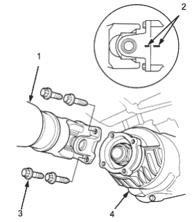
- 1. PROPELLER SHAFT
- 2. Mark
- 3. 12 POINT BOLT
- 4. REAR DIFFERENTIAL
- 5.Hold the stabiliser link ball joint with a hexagonal wrench and remove the flange nut, then separate the front stabiliser link and front stabiliser.
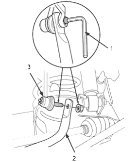
- 1. HEXAGONAL WRENCH
- 2. FRONT STABILISER
- 3. FRONT STABILISER LINK
- 6.Disconnect the breather tube from the rear differential.
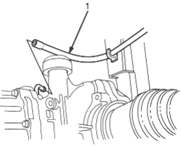
- 1. BREATHER TUBE
- 7.Remove the four rear differential mount A mounting bolts.
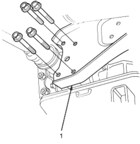
- 1. REAR DIFFERENTIAL MOUNT A
PDF p. 747 · 15-16
- 8.Remove the two rear differential mount B mounting bolts.
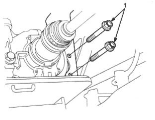
- 1. MOUNTING BOLTS
- 9.Pry the driveshaft assembly with a screwdriver, as shown, to force the set ring at the driveshaft end past the groove. Be careful not to damage the oil seals when prying.
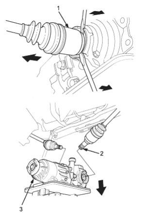
- 1. DRIVESHAFT
- 2. SET RING, Replace
- 3. REAR DIFFERENTIAL
- 10.Lower the rear differential on the transmission jack.
Leak Repair
- 1.Remove the bolts in a crisscross pattern, then remove the differential housing.
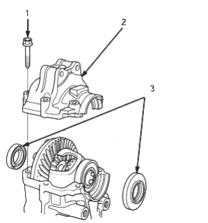
- 1. 8 x 1.25 mm, 22 Nm (2.2 kgf/m, 16 lbf/ft)
- 2. DIFFERENTIAL HOUSING
- 3. OIL SEALS, Replace
- 2.Apply liquid gasket to the sealing surface of the differential housing and note the following items:
- Use liquid gasket (P/N 0Y740-99986).
- Remove any dirt or fluid from the sealing surface.
- If 20 minutes have passed after applying liquid gasket, reapply it before you assemble the housing. Allow it to cure at least 30 minutes after assembly before filling differential with fluid.
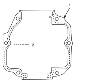
- 1. DIFFERENTIAL HOUSING
- 2. Apply Liquid Gasket
- 3.Install the differential housing, then torque the bolts in a crisscross pattern in several steps.
- 4.Install the oil seals (See page 15-18).
PDF p. 748 · 15-17
Illustrated Index
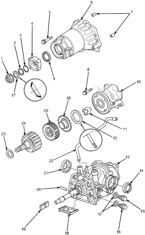
- 1. LOCKNUT, 24 mm Replace
118 Nm, (12.0 kgf/m, 87 lbf/ft) - 2. BACK-UP RING
- 3. O-RING, Replace
- 4. COMPANION FLANGE
- 5. 6 x 1.0 mm, 12 Nm (1.2 kgf/m, 8.7 lbf/ft)
- 6. TORQUE CONTROL DIFFERENTIAL
- 7. DOWEL PINS
- 8. 6 x 1.0 mm, 12 Nm (1.2 kgf/m, 8.7 lbf/ft)
- 9. OIL SEAL, Replace
- 10. OIL PUMP BODY ASSEMBLY
- 11. OIL PUMP DRIVESHAFT
- 12. THRUST NEEDLE BEARING
- 13. DIFFERENTIAL CARRIER
ASSEMBLY - 14. OIL SEAL, Replace
- 15. OIL FILLER PLUG, 47 Nm (4.8 kgf/m, 35 lbf/ft)
- 16. DRAIN PLUG, 47 Nm (4.8 kgf/m, 35 lbf/ft)
- 17. WASHERS, Replace
- 18. OIL STRAINER
- 19. MAGNET
- 20. OIL PUMP PIN
- 21. OIL SEAL, Replace
- 22. BREATHER TUBE
- 23. SHIM, 30 mm
- 24. CLUTCH GUIDE
- 25. CLUTCH HUB/PLATES/DISCS
- 26. PRESSURE PLATE
- 27. DISC SPRING WASHER, 24 mm
PDF p. 749 · 15-18
Oil Seals Replacement
- 1.Remove the oil seals from the differential housing. Right side:
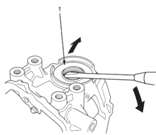
- 1. OIL SEAL, Replace
Left side:
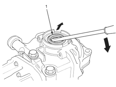
- 1. OIL SEAL, Replace
- 2.Install the oil seals squarely using the special tools. Be careful no to damage the lip of the oil seals. Right side: Installation depth of the oil seal is 9 mm (0.35 in) below the edge of the differential housing.
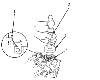
- 1. DIFFERENTIAL HOUSING
- 2. HANDLE DRIVER, 07749-0010000
- 3. DRIVER ATTACHMENT, 78 x 80 mm, 07NAD-PX40100
- 4. OIL SEAL
Left side: Install the oil seal flush with the edge of the differential carrier assembly.
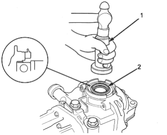
- 1. OIL SEAL DRIVER, 07GAD-PH70201
- 2. OIL SEAL
PDF p. 750 · 15-19
- 3.Remove the oil seal from the torque control differential case.
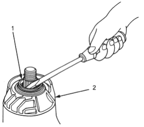
- 1. OIL SEAL, Replace
- 2. TORQUE CONTROL DIFFERENTIAL CASE
- 4.Install the oil seal squarely using the special tool. Be careful not to damage the lip of the oil seal.
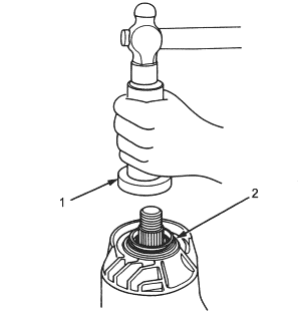
- 1. OIL SEAL DRIVER, 07JAD-PL90100
- 2. OIL SEAL, Replace
Disassembly
- 1.Remove the drain plug and the oil filler plug.
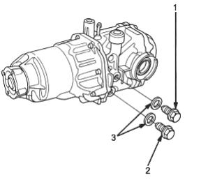
- 1. OIL FILLER PLUG
- 2. DRAIN PLUG
- 3. WASHERS, Replace
- 2.Raise the locknut from the groove of the clutch guide, making sure that the tab completely clears the groove to prevent damaging the clutch guide.
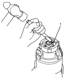
- 1. LOCKNUT, 24 mm, Replace
PDF p. 751 · 15-20
- 3.Install the special tool on the companion flange.
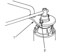
- 1. COMPANION FLANGE HOLDER, 07PAB-0020000
- 2. 8 x 1.25 mm, 32 Nm (3.3 kgf/m, 24 lbf/ft)
- 4.Loosen the locknut counterclockwise so that its tab comes out from the groove in the clutch guide.
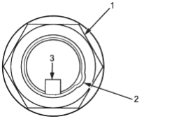
- 1. LOCKNUT, 24 mm
- 2. Tab
- 3. Groove
- 5.Tighten the locknut until its tab aligns with the groove.
- 6.Remove any dirt from inside of the groove in the clutch guide, then loosen the locknut.
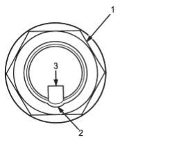
- 1. LOCKNUT, 24 mm
- 2. Tab
- 3. Groove
- 7.Remove the locknut, the disc spring washer, the back-up ring, the O-ring and the companion flange.
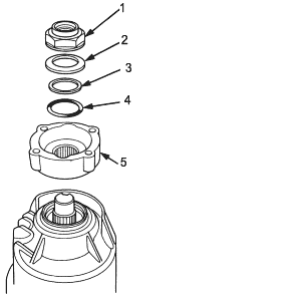
- 1. LOCKNUT, 24 mm, Replace
- 2. DISC SPRING WASHER, 24 mm
- 3. BACK-UP RING
- 4. O-RING, Replace
- 5. COMPANION FLANGE
- 8.Remove the torque control differential case and the dowel pins.
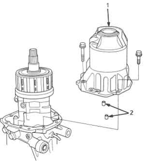
- 1. TORQUE CONTROL DIFFERENTIAL CASE
- 2. 6 x 10 mm DOWEL PINS
PDF p. 752 · 15-21
- 9.Remove the shim and the clutch guide.
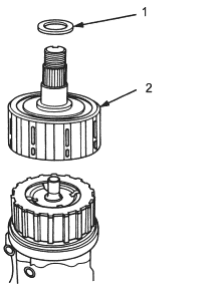
- 1. SHIM, 30 mm
- 2. CLUTCH GUIDE
- 10.Remove the clutch hub/plates/discs and the pressure plate.
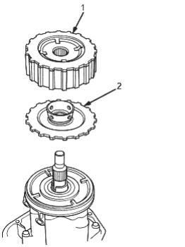
- 1. CLUTCH HUB/PLATES/DISCS
- 2. PRESSURE PLATE
- 11.Remove the thrust needle bearing and the oil pump driveshaft.
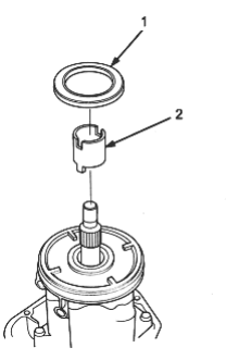
- 1. THRUST NEEDLE BEARING
- 2. OIL PUMP DRIVESHAFT
- 12.Remove the oil pump body assembly, the oil pump pin, the magnet and the oil strainer.
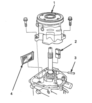
- 1. OIL PUMP BODY ASSEMBLY
- 2. MAGNET
- 3. OIL PUMP PIN
- 4. OIL STRAINER
Inspect for damage or clogging.
PDF p. 753 · 15-22
Reassembly
- 1.Apply CVT fluid to the rubber of the oil strainer, then install the oil strainer, the magnet and the oil pump pin to the differential carrier.
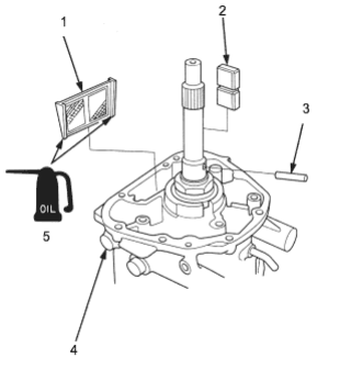
- 1. OIL STRAINER
- 2. MAGNET
- 3. OIL PUMP PIN
- 4. DIFFERENTIAL CARRIER ASSEMBLY
- 5. CVT Fluid
- 2.Align the oil pump pin with the groove of the rear oil pump in the pump body assembly, then install the oil pump body assembly to the differential carrier assembly.
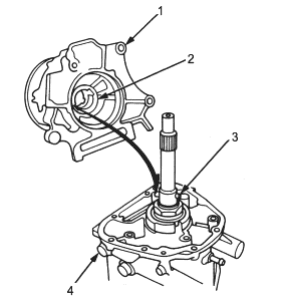
- 1. OIL PUMP BODY ASSEMBLY
- 2. REAR OIL PUMP
- 3. OIL PUMP PIN
- 4. DIFFERENTIAL CARRIER ASSEMBLY
- 3.Tighten the oil pump body assembly mounting bolts.
- 4.Install the oil pump driveshaft by aligning the projection of the oil pump driveshaft with the groove of the front oil pump in the oil pump body assembly.
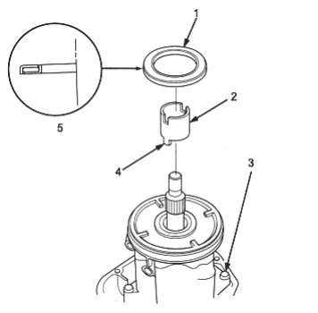
- 1. THRUST NEEDLE BEARING
- 2. OIL PUMP DRIVESHAFT
- 3. 6 x 1.0 mm, 12 Nm (1.2 kgf/m, 8.7 lbf/ft)
- 4. Projection
- 5. Install in this direction
- 5.Install the thrust needle bearing.
- 6.Install the pressure plate assembly by aligning the projection of the pressure plate with the groove of the oil pump driveshaft.
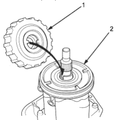
- 1. PRESSURE PLATE
- 2. OIL PUMP DRIVESHAFT
PDF p. 754 · 15-23
- 7.Install the clutch hub/plates/discs then align the projection of the plates with the discs.
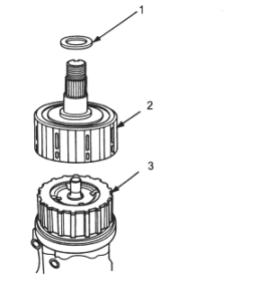
- 1. SHIM, 30 mm
- 2. CLUTCH GUIDE
- 3. CLUTCH HUB/PLATES/DISCS
- 8.Install the clutch guide and the 30 mm shim.
- 9.Apply liquid gasket to the sealing surface of the torque control differential case, and note the following items.
- Use liquid gasket (P/N 0Y740-99986).
- Remove any dirt or fluid from the sealing surface.
- If 20 minutes have passed after applying liquid gasket, reapply it before you assemble the housing. Allow it to cure at least 30 minutes after assembly before filling differential with fluid.
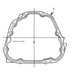
- 1. TORQUE CONTROL DIFFERENTIAL CASE
- 2. Apply liquid gasket
- 10.Install the dowel pins and torque control differential.
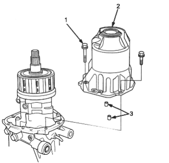
- 1. 6 x 1.0 mm, 12 Nm (1.2 kgf/m, 8.7lbf/ft)
- 2. TORQUE CONTROL DIFFERENTIAL CASE
- 3. DOWEL PINS
- 11.
Install the companion flange, O-ring, back-up ring, disc spring washer and the locknut.
NOTE: Apply ATF to the O-ring.
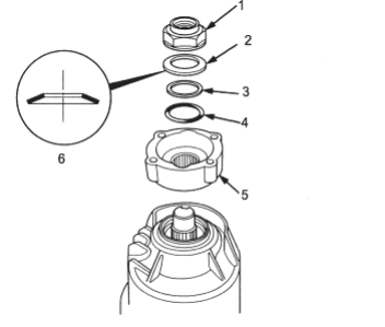
- 1. LOCKNUT, 24 mm, Replace
- 2. DISC SPRING WASHER, 24 mm
- 3. BACK-UP RING
- 4. O-RING, Replace
- 5. COMPANION FLANGE
- 6. Install in this direction
PDF p. 755 · 15-24
- 12.
Install the special tool to the companion flange, then tighten the locknut to specified torque.
TORQUE: 118 Nm (12.0 kgf/m, 87 lbf/ft)
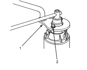
- 1. COMPANION FLANGE HOLDER, 07PAB-0020000
- 2. 8 x 1.25 mm, 32 Nm (3.3 kgf/m, 24 lbf/ft)
- 13.Stake the locknut tab into the groove in the clutch guide.
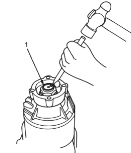
- 1. LOCKNUT, 24 mm
- 14.Install the drain plug and the oil filler plug with new washers.
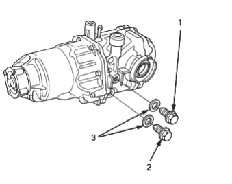
- 1. OIL FILLER PLUG, 47 Nm (4.8 kgf/m, 35 lbf/ft)
- 2. DRAIN PLUG, 47 Nm (4.8 kgf/m, 35 lbf/ft)
- 3. WASHERS, Replace
PDF p. 756 · 15-25
Illustrated Index
NOTE: When installing the rear differential and mount assemblies, tighten the rear differential mount B mounting bolts (A) first, then the rear differential mount rubber A mounting bolts (B).
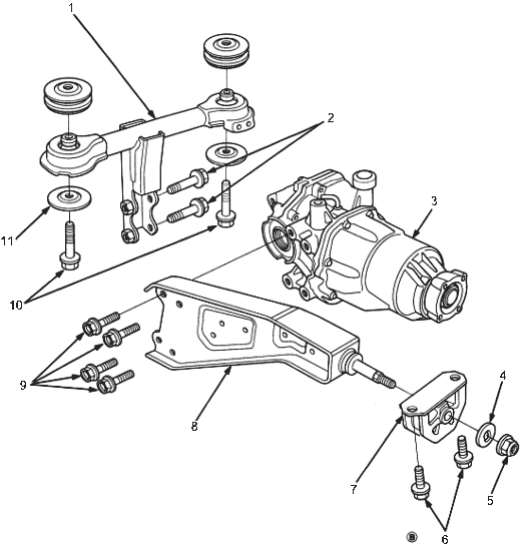
- 1. REAR DIFFERENTIAL MOUNT B
- 2. 12 x 1.25 mm, 59 Nm (6.0 kgf/m, 43 lbf/ft)
- 3. REAR DIFFERENTIAL
- 4. WASHER
- 5. 12 x 1.25 mm, 59 Nm (6.0 kgf/m, 43 lbf/ft)
- 6. (B) 10 x 1.25 mm, 44 Nm (4.5 kgf/m, 33 lbf/ft)
- 7. REAR DIFFERENTIAL MOUNT RUBBER A
- 8. REAR DIFFERENTIAL MOUNT BRACKET A
- 9. 12 x 1.25 mm, 59 Nm (6.0 kgf/m, 43 lbf/ft)
- 10. (A) 10 x 1.25 mm, 49 Nm (5.0 kgf/m, 36 lbf/ft)
- 11. PLATE
PDF p. 757 · 15-26
Installation
- 1.Place the rear differential on the transmission jack and raise it to the mounting level.
- 2.Clean the areas where the driveshaft contacts the differential thoroughly with solvent or carburettor cleaner and dry with compressed air. Insert the inboard end of the driveshaft into the differential until the set ring locks in the groove.
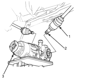
- 1. DRIVESHAFT
- 2. SET RING, Replace
- 3. REAR DIFFERENTIAL
- 3.Install the two rear differential mount B mounting bolts.
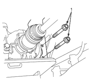
- 1. 12 x 1.25 mm, 59 Nm (6.0 kgf/m, 43 lbf/ft)
- 4.Install the four rear differential mount A mounting bolts.
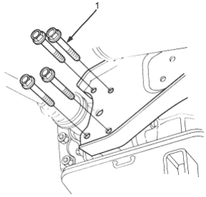
- 1. 12 x 1.25 mm, 59 Nm (6.0 kgf/m, 43 lbf/ft)
- 5.Connect the breather tube to the rear differential.
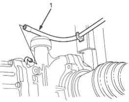
- 1. BREATHER TUBE
PDF p. 758 · 15-27
- 6.Hold the stabiliser link ball joint pin with a hexagonal wrench and install the flange nut.
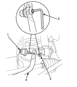
- 1. STABILISER LINK
- 2. HEXAGONAL WRENCH
- 3. 10 x 1.25 mm, 29 Nm (3.0 kgf/m, 22 lbf/ft)
- 4. REAR STABILISER
- 7.Install the propeller shaft to the rear differential by aligning the reference marks.
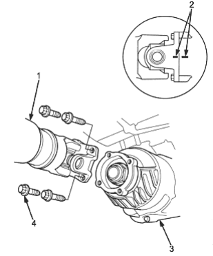
- 1. PROPELLER SHAFT
- 2. MARKS
- 3. REAR DIFFERENTIAL
- 4. 8 x 1.25 mm, 32 Nm (3.3 kgf/m, 24 lbf/ft)
- 8.Refill the rear differential oil (See page 15-14).