PDF p. 648 · 14-94
- 1.Shift to N position
- 2.Disconnect the battery negative terminal, then disconnect the positive terminal.
- 3.Remove the battery hold-down bracket, then remove the battery.
- 4.Remove the battery base.
- 5.Remove the drain plug and drain the transmission fluid.
- 6.Reinstall the drain plug and the new sealing washer.
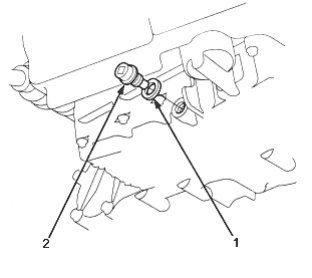
- 1. SEALING WASHER Replace.
- 2. DRAIN PLUG 18 x 1.5 mm, 49 Nm (5.0 kgf/m, 36 lbf/ft)
- 7.Remove the harness clamp from the clamp bracket, then disconnect the starter cables.
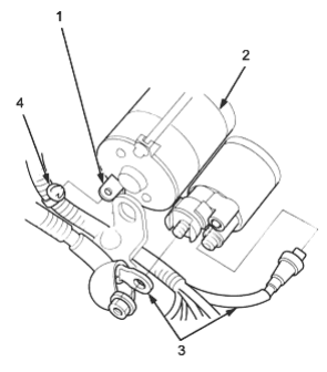
- 1. CLAMP BRACKET
- 2. STARTER
- 3. STARTER CABLES
- 4. HARNESS CLAMP
- 8.Remove the transmission ground cable terminals and the radiator hose clamp from the transmission hanger, then disconnect the solenoid harness connector and the drive pulley speed sensor connector.
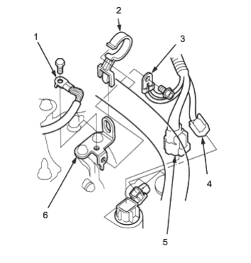
- 1. TRANSMISSION GROUND CABLE TERMINAL
- 2. RADIATOR HOSE CLAMP
- 3. TRANSMISSION GROUND CABLE TERMINAL
- 4. DRIVE PULLEY SPEED SENSOR CONNECTOR
- 5. SOLENOID HARNESS CONNECTOR
- 6. TRANSMISSION HANGER
PDF p. 649 · 14-95
- 9.Remove the clip from the shift cable end, then separate the cable end from the control lever..
- 10.Remove the shift cable bracket with shift cable. Do not bend the shift cable excessively.
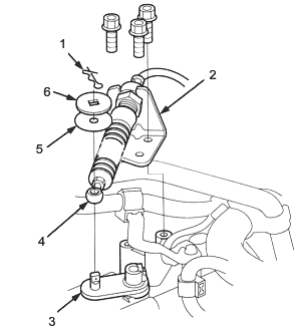
- 1. CLIP
- 2. SHIFT CABLE BRACKET
- 3. CONTROL LEVER
- 4. SHIFT CABLE END
- 5. PLASTIC WASHER
- 6. WASHER
- 11.Remove the harness clamp bracket, then disconnect the engine coolant temperature (ECT) sensor, secondary gear shaft speed sensor, driven pulley speed sensor and vehicle speed sensor (VSS) connectors.
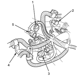
- 1. VSS CONNECTOR
- 2. ECT SENSOR CONNECTOR
- 3. DRIVEN PULLEY SPEED SENSOR CONNECTOR
- 4. HARNESS CLAMP BRACKET
- 5. SECONDARY GEAR SHAFT SPEED SENSOR CONNECTOR
- 12.Remove the distributor.
- 13.Remove the transmission housing mounting bolts.
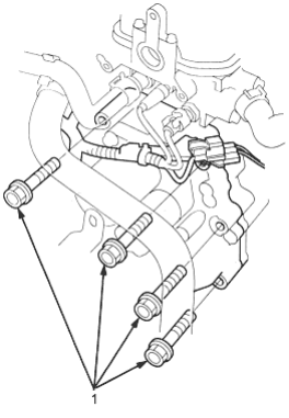
- 1. TRANSMISSION HOUSING MOUNTING BOLTS
- 14.Remove the splash shield.
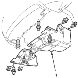
- 1. SPLASH SHIELD
PDF p. 650 · 14-96
- 15.Install a 5 mm Allen wrench into the tip of the ball joint pins, then remove the flange nuts from the ball joint pins on the front stabiliser link. Separate the front stabiliser links from the lower arms.
- 16.Remove the cotter pins and ball joint nuts, then separate the knuckles from the lower arms (see section 18).
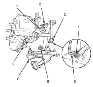
- 1. BALL JOINT NUT
- 2. COTTER PIN Replace.
- 3. FRONT STABILISER LINK
- 4. BALL JOINT PIN
- 5. ALLEN WRENCH, 5 mm
- 6. FLANGE NUT Replace.
- 7. LOWER ARM
- 8. KNUCKLE
- 17.Remove the rear beam.
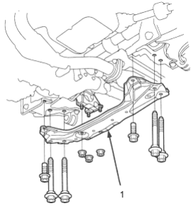
- 1. REAR BEAM
- 18.Pry the driveshaft out of the differential and the intermediate shaft, then pull on the inboard joints to remove the right driveshaft from the differential and to remove the left driveshaft from the intermediate shaft (see section 16).
- 19.Move the right driveshaft to the front side.
- 20.Coat all precision finished surfaces with clean engine oil, then tie the plastic bags over the driveshaft ends.
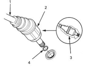
- 1. DRIVESHAFT
- 2. INBOARD JOINT
- 3. PLASTIC BAG
- 4. SET RING Replace.
- 21.Remove the exhaust pipe A.
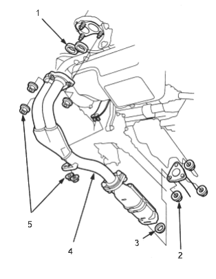
- 1. GASKET Replace.
- 2. SELF-LOCKING NUT Replace.
- 3. GASKET Replace.
- 4. EXHAUST PIPE A
- 5. SELF-LOCKING NUT Replace.
PDF p. 651 · 14-97
- 22.Make a reference mark across the propeller shaft and the transfer assembly flange, then separate the propeller shaft from the transfer assembly for 4WD model.
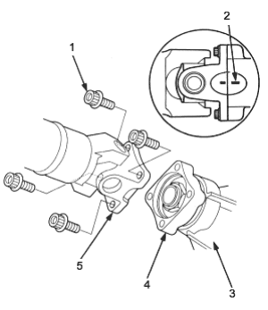
- 1. 8 x 1.25 mm, Replace.
- 2. REFERENCE MARK
- 3. TRANSFER ASSEMBLY
- 4. TRANSFER FLANGE
- 5. PROPELLER SHAFT
- 23.Remove the intermediate shaft.
- 24.Coat all precision finished surfaces with clean engine oil, then tie the plastic bags over the both ends of the intermediate shaft.
- 25.Remove the rear stiffener.
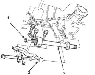
- 1. SET RING Replace.
- 2. INTERMEDIATE SHAFT
- 3. REAR STIFFENER
- 26.Remove the ATF cooler hoses from the ATF cooler lines. Turn the ends of the ATF cooler hoses up to prevent ATF flowing out, then plug the ATF cooler hoses and lines. Check for any signs of leakage at the hose points.
- 27.Remove the right front mount/bracket.
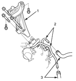
- 1. RIGHT FRONT MOUNT/BRACKET
- 2. ATF COOLER LINES
- 3. ATF COOLER HOSES
- 28.Remove the front stiffener and flywheel cover.
- 29.Remove the eight drive plate bolts one at a time while rotating the crankshaft pulley.
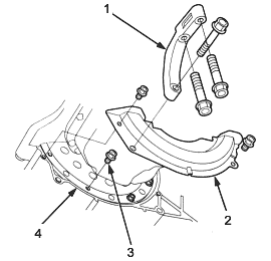
- 1. FRONT STIFFENER
- 2. FLYWHEEL COVER
- 3. DRIVE PLATE BOLT
- 4. DRIVE PLATE
PDF p. 652 · 14-98
- 30.Remove the rear mount/bracket.
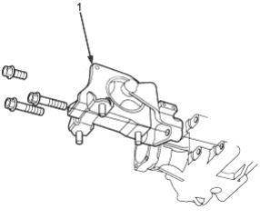
- 1. REAR MOUNT BRACKET
- 31.Attach a hoist bracket to the engine, then lift the engine slightly.
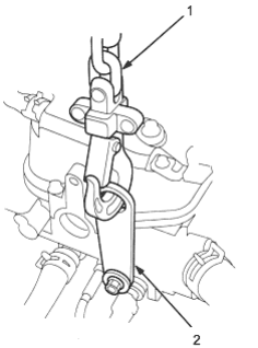
- 1. HOIST CHAIN
- 2. HOIST BRACKET
- 32.Place a jack under the transmission and raise the transmission just enough to take weight off mounts.
- 33.Remove the transmission mount bracket.
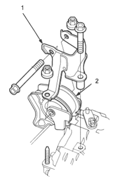
- 1. TRANSMISSION MOUNT BRACKET
- 2. TRANSMISSION MOUNT
- 34.Remove the transmission housing mounting bolt.
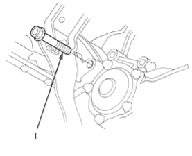
- 1. TRANSMISSION HOUSING MOUNTING BOLT
PDF p. 653 · 14-99
- 35.Pull the transmission away from the engine until it clears the dowel pin.
- 36.Remove the starter from the transmission.
- 37.Remove the flywheel from the transmission.
- 38.Inspect the drive plate and replace it if damaged.
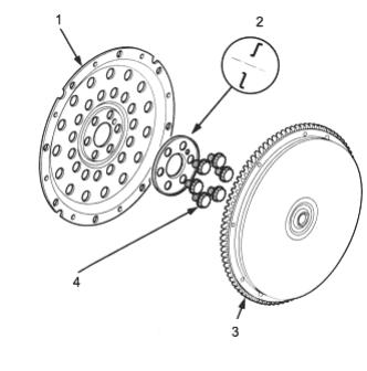
- 1. DRIVE PLATE
- 2. WASHER Install in this direction.
- 3. FLYWHEEL/RING GEAR Inspect the ring gear teeth for excessive wear.
- 4. 12 x 1.0 mm, 74 Nm (7.5 kgf/m 54 lbf/ft) Tighten in a criss-cross pattern.