PDF p. 643 · 14-89
- 1.Raise the front of the vehicle and make sure it is securely supported.
- 2.Set the parking brake and block both rear wheels securely.
- 3.Shift to N position.
- 4.Make a reference mark across the propeller shaft and the transfer companion flange.
- 5.Separate the propeller shaft from the transfer assembly.
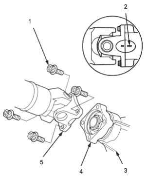
- 1. 8 x 1.25 mm, 32 Nm (3.3 kgf/m, 24 lbf/ft)
- 2. REFERENCE MARK
- 3. TRANSFER ASSEMBLY
- 4. COMPANION FLANGE
- 5. PROPELLER SHAFT
- 6.
Set a dial indicator on the transfer companion flange, then measure the transfer gear backlash.
STANDARD: 0.06 - 0.16 mm (0.002 - 0.0006 in)
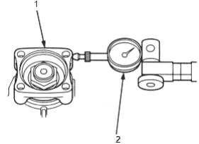
- 1. COMPANION FLANGE
- 2. DIAL INDICATOR
- 7.If the measurement is out of standard, remove the transfer assembly and adjust transfer gear backlash (See Page 14-143).
- 8.Check the entire transfer assembly for damage and fluid leaks.
- If the fluid leaks between the transfer housing and the transfer cover, remove the transfer cover and replace the O-ring.
- If the fluid leaks between the flywheel housing and the transfer housing, remove the transfer assembly and replace the O-ring.
If the fluid leaks between the transfer companion flange and the oil seal, remove the transfer assembly and replace the oil seal and O-ring on the transfer shaft. If the oil seal replacement is required, assemble the transfer assembly with checking and adjusting the transfer gear tooth contact, transfer gear backlash, the tapered roller bearing starting torque and the total starting torque (See Page 14-140) through (See Page 14-149).
Do not replace the oil seal with the transfer assembly on the transmission.