PDF p. 641 · 14-87
- 1.Raise the front of the vehicle and make sure it is securely supported.
- 2.Set the parking brake and block both rear wheels securely.
- 3.Remove the drain plug and drain the transmission fluid. Reinstall the drain plug with a new sealing washer (See Page 14-84).
- 4.Disconnect the solenoid harness connector.
- 5.Disconnect the ATF cooler inlet hose at the cooler line. Turn the end of the hose up to prevent ATF from flowing out, then plug the hose and line.
- 6.Remove the right front mount/bracket.
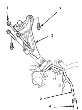
- 1. 10 x 1.25 mm, 54 Nm (5.5 kgf/m, 40 lbf/ft)
- 2. 10 x 1.25 mm, 44 Nm (4.5 kgf/m, 33 lbf/ft)
- 3. RIGHT FRONT MOUNT/BRACKET
- 4. ATF COOLER INLET HOSE
- 5. ATF COOLER INLET LINE
- 7.Remove the ATF cooler inlet line bracket bolt.
- 8.Remove the ATF pan (14 bolts).
- 9.Remove the ATF strainer, then remove the bolt securing the solenoid harness connector.
- 10.Remove the lower valve body assembly (8 bolts). Torque Specification: 6 x 1.0 mm bolts in this illustration 12 Nm (1.2 kgf/m 8.7 lbf/ft)
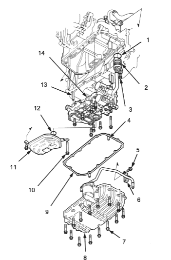
- 1. O-RING Replace
- 2. SOLENOID HARNESS CONNECTOR
- 3. 6 x 1.0 mm
- 4. DOWEL PIN
- 5. 8 x 1.25 mm, 26 Nm (2.7 kgf/m, 20 lbf/ft)
- 6. ATF COOLER INLET LINE BRACKET
- 7. 6 x 1.0 mm
- 8. ATF PAN
- 9. ATF PAN GASKET Replace
- 10. 6 X 1.0 MM
- 11. ATF STRAINER
- 12. O-RING Replace
- 13. DOWEL PIN
- 14. LOWER VALVE BODY ASSEMBLY
- 11.
Install the lower valve body assembly in the reverse order of the removal.
NOTE:
- Replace the following parts when installing:
- O-rings
- ATF pan gasket
- Sealing washer
- Replace the following parts when installing:
- 12.Calibrate the feedback signal for the start clutch control in the PCM (See Page 14-71).