PDF p. 726 · 14-168
- 1.Remove the front console (see section 20).
- 2.Shift to N position, then remove the lock pin from the adjuster.
NOTE: LHD model is shown; RHD is similar.
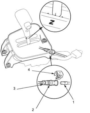
- 1. SHIFT CABLE
- 2. ADJUSTER
- 3. LOCKNUT, 7 Nm (0.7 kgf/m, 5 lbf/ft)
- 4. LOCK PIN
- 3.Remove the clip from the shift cable end, then separate the able end from the control lever.
- 4.Remove the shift cable bracket with shift cable. Do not bend the shift cable excessively.
- 5.Loosen the locknut, then remove the shift cable from the shift cable bracket.
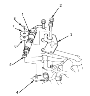
- 1. LOCKNUT, 29 Nm (3.0 kgf/m, 22 lbf/ft)
- 2. 8 x 1.25 mm, 26 Nm (2.7 kgf/m, 20 lbf/ft)
- 3. SHIFT CABLE BRACKET
- 4. CONTROL LEVER
- 5. SHIFT CABLE END
- 6. PLASTIC WASHER
- 7. WASHER
- 8. CLIP
- 6.Remove the rear beam.
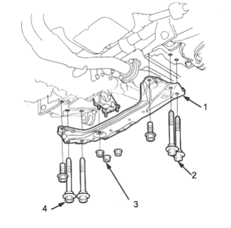
- 1. REAR BEAM
- 2. 12 x 1.25 mm, 64 Nm (6.5 kgf/m, 47 lbf/ft)
- 3. 10 x 1.25 mm, 38 Nm (3.9 kgf/m, 28 lbf/ft)
- 4. 12 x 1.25 mm, 64 Nm (6.5 kgf/m, 47 lbf/ft)
PDF p. 727 · 14-169
- 7.Remove the bolts securing the shift cable brackets.
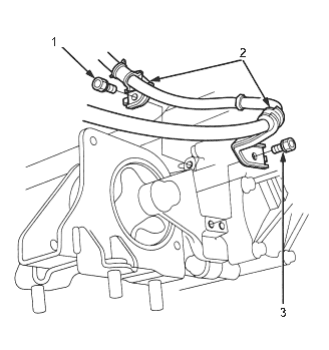
- 1. 6 x 10 mm, 12 Nm (1.2 kgf/m, 8.7 lbf/ft)
- 2. SHIFT CABLE BRACKETS
- 3. 6 x 1.0 mm, 12 Nm (1.2 kgf/m, 8.7 lbf/ft)
- 8.Remove the shift cable bracket.
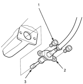
- 1. 6 x 1.0 mm, 12 Nm (1.2 kgf/m, 8.7 lbf/ft)
- 2. SHIFT CABLE BRACKET
- 3. SHIFT CABLE
- 9.Replace the shift cable, then install the new cable in the reverse order of removal. Do not bend the shift cable excessively.
- 10.Check the shift cable adjustment (See Page 14-167).
Shift Lever
Removal/Installation
- 1.Raise the front of the vehicle and make sure it is securely supported.
- 2.Set the parking brake and block both rear wheels securely.
- 3.Remove the front console (see section 20).
- 4.Shift to N position, then remove the lock pin from the adjuster.
- 5.Disconnect the A/T gear position switch connector.
- 6.Disconnect the shift lock solenoid and parking pin switch connectors for KQ and KU models.
- 7.Remove the nuts securing the shift lever assembly from under-body.
- 8.Install the shift lever assembly in the reverse order of removal.
- 9.Check the shift cable adjustment (See Page 14-167).
NOTE: RHD model is shown; LHD is similar
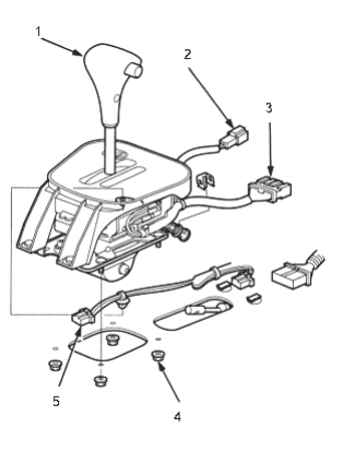
- 1. SHIFT LEVER ASSEMBLY
- 2. PARKING PIN SWITCH CONNECTOR
- 3. A/T GEAR POSITION SWITCH CONNECTOR
- 4. 6 x 1.0 mm, 9.8 Nm (1.0 kgf/m, 7.2 lbf/ft)
- 5. SHIFT LOCK SOLENOID CONNECTOR