PDF p. 692 · 14-135
- 1.Remove the transfer covers A and B.
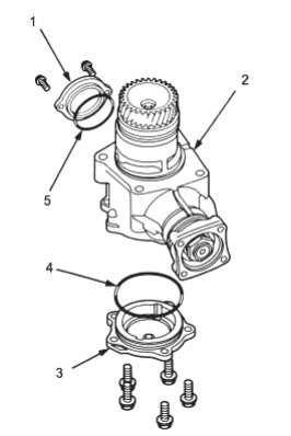
- 1. TRANSFER COVER B
- 2. TRANSFER HOUSING
- 3. TRANSFER COVER A
- 4. 0-RING, Replace
- 5. O-RING, Replace
- 2.Cut the lock tabs of the locknut using a chisel.
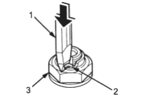
- 1. CHISEL
- 2. LOCK TAB
- 3. LOCKNUT
- 3.Put a 14 mm Allen wrench in the gear side of the transfer shaft, then secure the Allen wrench in a bench vice.
- 4.Remove the transfer shaft locknut and the conical spring washer. The transfer shaft locknut has left-hand threads.
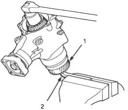
- 1. TRANSFER SHAFT
- 2. 14 mm, ALLEN WRENCH
- 5.Remove the transfer shaft, transfer drive gear, 25 mm thrust shim, transfer shaft collar and tapered roller bearing from the transfer housing.
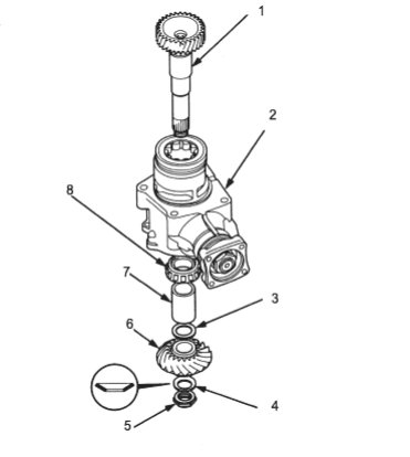
- 1. TRANSFER SHAFT
- 2. TRANSFER HOUSING
- 3. THRUST SHIM, 25 mm, Selective part
- 4. CONICAL SPRING WASHER, Replace
- 5. LOCKNUT, Replace
- 6. TRANSFER DRIVE GEAR
- 7. TRANSFER SHAFT COLLAR
- 8. TAPERED ROLLER BEARING
PDF p. 693 · 14-136
- 6.Secure the transfer housing in a bench vice with soft jaws. To prevent damage to the transfer housing, always use soft jaws or equivalent materials between the transfer housing and the vice.
- 7.Install the special tool on the companion flange, then loosen the transfer driven gear shaft locknut.
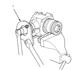
- 1. COMPANION FLANGE HOLDER 07PAB-0020000
- 8.Remove the transfer driven gear shaft locknut, conical spring washer, back-up ring, O-ring and companion flange.
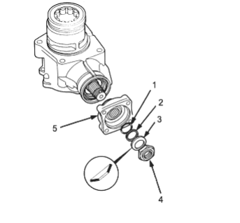
- 1. O-RING, Replace
- 2. BACK-UP RING
- 3. CONICAL SPRING WASHER, Replace
- 4. TRANSFER DRIVEN GEAR SHAFT LOCKNUT, Replace
- 5. COMPANION FLANGE
- 9.Remove the transfer driven gear shaft, then remove the transfer spacer from the transfer driven gear shaft.
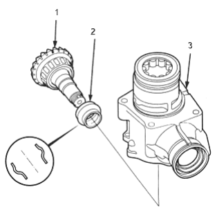
- 1. TRANSFER DRIVEN GEAR SHAFT
- 2. TRANSFER SPACER, Replace
- 3. TRANSFER HOUSING
- 10.Remove the oil seal and the tapered roller bearing from the transfer housing.
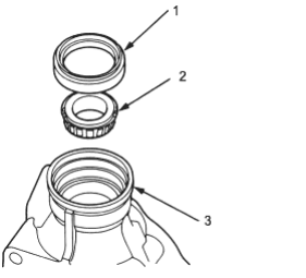
- 1. OIL SEAL, Replace
- 2. TAPERED ROLLER BEARING
- 3. TRANSFER HOUSING