PDF p. 691 · 14-134
NOTE: To prevent damage to the transfer housing, always use soft jaws or equivalent materials between the transfer housing and the vice.
Transfer Gear (Hypoid gear) Backlash Measurement
- 1.Set a dial indicator on the companion flange as shown.
- 2.
Measure the transfer gear backlash.
STANDARD: 0.06 - 0.16 mm (0.02 - 0.06 in)
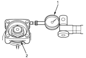
- 1. DUAL INDICATOR
- 2. COMPANION FLANGE
Total Starting Torque Measurement
- 3.Rotate the companion flange several times to seat the tapered roller bearing.
- 4.
Measure the starting torque (companion flange side) using a torque wrench as shown.
STANDARD:
2.68 - 3.47 Nm (27.3 - 35.4 kgf/cm, 23.7 - 30.7 lbf/in)
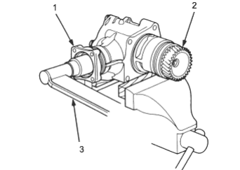
- 1. COMPANION FLANGE
- 2. TRANSFER SHAFT
- 3. TORQUE WRENCH
Transfer Gear (Hypoid gear) Tooth Contract Inspection
- 5.Remove transfer cover B, then apply Prussian Blue to both sides of the transfer gear teeth lightly and evenly.
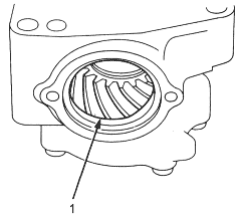
- 1. TRANSFER DRIVE GEAR
- 6.Rotate the companion flange in both directions until the transfer gear rotates one full turn in both directions.
- 7.Check the transfer gear tooth contact pattern.
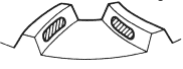
- 8.If the measurements or the tooth contact pattern are not within the standard, disassembly the transfer assembly, replace worn or damaged parts and reassemble it.