PDF p. 686 · 14-129
- 1.
To remove the driven pulley shaft bearing from the transmission housing, expand the snap ring with snap ring pliers, then push the bearing out using the special tools and a press as shown.
NOTE: Do not remove the snap ring unless it is necessary to clean the groove in the housing.
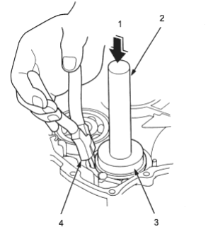
- 1. PRESS
- 2. HANDLE DRIVER, 07749-0010000
- 3. DRIVER ATTACHMENT, 72 x 75 mm, 07746-0010600
- 4. SNAP RING PLIERS, 07LGC-0010100
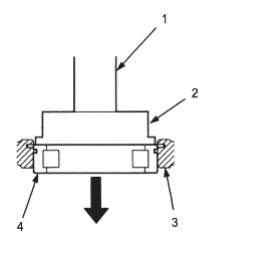
- 1. HANDLE DRIVER, 07749-0010000
- 2. DRIVER ATTACHMENT, 72 x 75 mm, 07746-0010600
- 3. TRANSMISSION HOUSING
- 4. BEARING
- 2.
Expand the snap ring with snap ring pliers, insert the new bearing part-way into the housing using the special tools and a press as shown. Install the bearing with the groove facing outside the housing.
NOTE: Coat all parts with CVT Fluid.
- 3.Release the pliers, then push the bearing down into the housing until the ring snaps in place around it, using the special tools as shown.
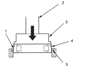
- 1. BEARING
- 2. DRIVER, 07749-0010000
- 3. ATTACHMENT, 72 x 75 mm, 07746-0010600
- 4. GROOVE
- 5. SNAP RING
- 4.After installing the bearing verify the following:
- The snap ring is seated in the bearing and housing grooves.
- The ring end gap is correct.
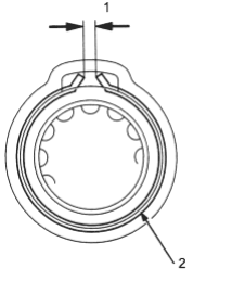
- 1. END GAP, 0 - 9 mm, (0 - 0.35 in)
- 2. SNAP RING