PDF p. 684 · 14-127
- 1.
Install the 2.50 mm (0.098 in) thick 80 mm set ring in the transmission housing.
NOTE: Do not install the oil seal.
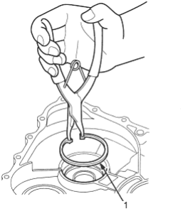
- 1. SET RING, 80 mm, Selective part.
- 2.Install the differential assembly into the transmission housing and drive it into the housing securely using the special tool.
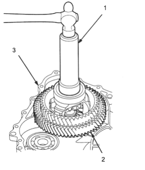
- 1. DRIVER 40 mm, I.D. 07746-0030100
- 2. DIFFERENTIAL ASSEMBLY
- 3. TRANSMISSION HOUSING
- 3.Install the flywheel housing with new gasket, dowel pins an connector bracket.
- 4.Tighten the bolts to the specified torque.
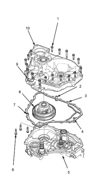
- 1. FLYWHEEL HOUSING MOUNTING BOLTS
8 x 1.25 mm, 29 Nm (3.0 kgf/m, 22 lbf/ft), 18 Bolts. - 2. DOWEL PIN, 12 x 20 mm
- 3. FLYWHEEL HOUSING GASKET
- 4. DOWEL PIN, 10 x 16 mm
- 5. TRANSMISSION HOUSING
- 6. FLYWHEEL HOUSING MOUNTING BOLTS
8 x 1.25 mm, 29 Nm (3.0 kgf/m, 22 lbf/ft), 3 Bolts - 7. DOWEL PIN, 10 x 16 mm
- 8. DIFFERENTIAL ASSEMBLY
- 9. CONNECTOR BRACKET
- 10. FLYWHEEL HOUSING
PDF p. 685 · 14-128
- 5.
Measure the side clearance between the 80 mm set ring and outer race of the ball bearing in the transmission housing.
STANDARD: 0 - 0.15 mm (0 - 0006 in)
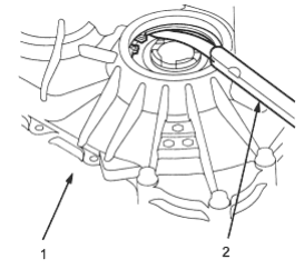
- 1. TRANSMISSION HOUSING
- 2. FEELER GAUGE
- 6.
If the clearance is more than the standard select a new set ring from the table and install it.
SET RING, 80 mm
| Part Number | Thickness |
| 90414-689-00 | 2.50 mm (0.098 in) |
| 90415-689-00 | 2.60 mm (0.102 in) |
| 90416-689-00 | 2.70 mm (0.106 in) |
| 90417-689-00 | 2.80 mm (0.110 in) |
| 90418-689-00 | 2.90 mm (0.114 in) |
| 90419-PH8-00 | 3.00 mm (0.118 in) |
NOTE: If the clearance measured in step 5 is standard, it is not necessary to perform steps 7 and 8.
- 7.Remove the flywheel housing.
- 8.Replace the 2.50 mm (0.098 in) set ring, 80 mm with the one of the correct thickness selected in step 5.
Flywheel Housing Input Shaft Oil Seal
Replacement
- 1.Remove the input shaft oil seal from the flywheel housing.
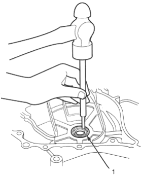
- 1. OIL SEAL
- 2.Install the oil seal in the flywheel housing using the special tools.
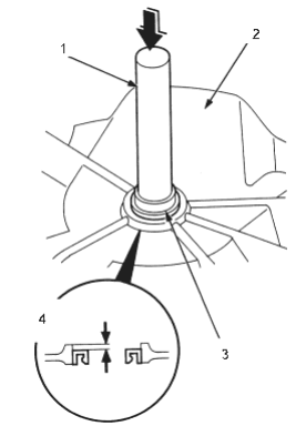
- 1. HANDLE DRIVER, 07749-0010000
- 2. FLYWHEEL HOUSING
- 3. DRIVER ATTACHMENT, 32 x 35 mm, 07746-0010100
- 4. Installed depth: 2.5 - 3.5 mm, (0.098 - 0.138 in)