PDF p. 559 · 14-4
The Continuously Variable Transmission (CVT/Honda Multi Matic) is an electronically controlled automatic transmission with drive and driven pulleys and a steel belt. The CVT/Honda Multi Matic provides non-stage speeds forward and one reverse. The entire unit is positioned in line with the engine.
Transmission
Around the outside of the flywheel is a ring gear which meshes with the starter pinion when the engine is being started. The transmission has four parallel shafts: the input shaft, the drive pulley shaft, the driven pulley shaft and the secondary gear shaft. The input shaft is in line with the engine crankshaft. The drive pulley shaft and the driven pulley shaft consist of movable and fixed face pulleys. Both pulleys are linked by the steel belt.
The input shaft includes the sun gear. The drive pulley shaft includes the forward clutch which mounts the carrier assembly on the forward clutch drum. The carrier assembly includes the pinion gears which mesh with the sun gear and the ring gear. The ring gear has a hub-mounted reverse brake disc.
The driven pulley shaft includes the start clutch and the secondary drive gear which is integral with the parking gear. The secondary gear shaft is positioned between the secondary drive gear and the final driven gear. The secondary gear shaft includes the secondary driven gear which services to change the rotation direction, because the drive pulley shaft and the driven pulley shaft rotate the same direction. When certain combinations of planetary gears in the transmission are engaged by the clutches and the reverse brake, power is transmitted from the drive pulley shaft to the driven pulley shaft to provide L, D, R.
Electronic Control
The electronic control system consists of a Powertrain Control Module (PCM, sensors, three linear solenoids and an inhibitor solenoid. Shifting is electronically controlled for comfort under all conditions. Also a Grade Logic Control System has been adopted to control shifting in D position while the vehicle is ascending or descending a slope. The PCM is located below the dashboard, under the kick panel on the passenger’s side.
Hydraulic Control
The lower valve body assembly includes the main valve body, the Pressure Low (PL) regulator valve body, the shift valve body, the start clutch control valve body and the secondary valve body. They are positioned on the lower part of the transmission housing.
The main valve body contains the Pressure High (PH) control valve, the lubrication valve and the pitot regulator valve.
The secondary valve body contains the PH regulator valve, the clutch reducing valve, the start clutch valve accumulator and the shift inhibitor valve. The PL regulator valve body contains the PL regulator valve and the PH-PL control valve which is joined with the PH-PL control linear solenoid. The inhibitor solenoid valve is bolted on the PL regulator valve body. The shift valve body contains the shift valve and the shift control valve, which is joined with the shift control linear solenoid. The start clutch control valve body contains the start clutch control valve, which is joined with the start clutch control linear solenoid. The linear solenoids and the inhibitor solenoid are controlled by the PCM. The manual valve body which contains the manual valve and the reverse inhibitor valve, is bolted on the intermediate housing.
The ATF pump assembly is located on the transmission housing and it is linked with the input shaft by the sprockets and the sprocket chain. The pulleys and the clutch receive fluid from their respective fee pipes and the reverse brake receives fluid from internal hydraulic circuit.
Shift Control Mechanism
Input from various sensors located throughout the vehicle determines which linear solenoid the PCM will activate. Activating the shift control linear solenoid changes the shift control valve pressure, causing the shift valve to move. This pressurises the drive pulley pressure to the drive pulley and the driven pulley pressure to the driven pulley and changes their effective pulley ratio. Activating the start clutch control linear solenoid moves the start clutch control valve. The start clutch control valve uncovers the port, providing pressure to the start clutch to engage it.
PDF p. 560 · 14-5
Gear Selection
The shift lever has five positions: P, PARK, R REVERSE, N NEUTRAL, D DRIVE and L LOW.
| Position | Description | |
|---|---|---|
| P PARK | Front wheels locked; parking brake pawl engaged with the | |
| parking gear on the driven pulley shaft. The start clutch and the | ||
| forward clutch released. | ||
| R REVERSE | Reverse; reverse brake engaged. | |
| N NEUTRAL | Neutral; the start clutch and the forward clutch released. | |
| D DRIVE | This position has two modes: Drive mode and Sport mode with | |
| switching the mode switch on the steering wheel. | ||
| ♦ | Drive mode with turning D mode switch on: | |
| General driving; the transmission automatically adjusts to keep | ||
| the engine at the best speed for driving conditions. | ||
| ♦ | Sport mode with turning S mode switch on: | |
| For rapid acceleration; the transmission selects a wider range of | ||
| ratios to give better acceleration. | ||
| L LOW | For engine braking and power for climbing; the transmission | |
| shifts into the lowest range of the ratios | ||
Starting is possible only in P and N positions through the use of a slide-type, neutral-safety switch.
Automatic Transaxle (A/T) Gear Position Indicator
The A/T gear position indicator in the instrument panel shows which gear has been selected without having to look down at the console.
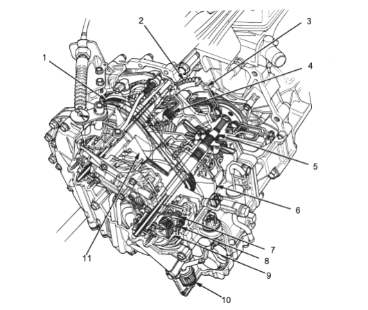
- 1. STEEL BELT
- 2. RING GEAR
- 3. FLYWHEEL
- 4. START CLUTCH
- 5. INPUT SHAFT
- 6. DRIVE PULLEY
- 7. FORWARD CLUTCH
- 8. REVERSE BRAKE
- 9. PLANETARY GEAR SET
- 10. ATF FILTER
- 11. DRIVEN PULLEY
PDF p. 561 · 14-6
Clutches/Reverse Brake/Planetary Gear/Pulleys
Clutches/Reverse Brake
The CVT uses the hydraulically-actuated clutches and brake to engage or disengage the transmission gears. When hydraulic pressure is introduced into the clutch drum and the reverse brake piston cavity, the clutch piston and the reverse brake piston move. This presses the friction discs and the steel plates together, locking them so they don’t slip. Power is then transmitted through the engaged clutch pack to its hub-mounted gear and through engaged ring gear to pinion gears.
Likewise, when the hydraulic pressure is bled from the clutch pack and the reverse brake piston cavity, the piston releases the friction discs and the steel plates, they are free to slide past each other. This allows the gear to spin independently on its shaft, transmitting no power.
Start Clutch
The start clutch, which is located at the end of the driven pulley shaft, engages/disengages the secondary drive gear.
The start clutch is supplied hydraulic pressure by its ATF feed pipes within the driven pulley shaft.
Forward Clutch
The forward clutch, which is located at the end of the drive pulley shaft, engages/disengages the sun gear.
The forward clutch is supplied hydraulic pressure by its ATF feed pipe within the drive pulley shaft.
Reverse Brake
The reverse brake, which is located inside the intermediate housing around the ring gear, locks the ring gear in R position. The reverse brake discs are mounted to the ring gear and the reverse brake plates are mounted to the intermediate housing. The reverse brake is supplied hydraulic pressure by a circuit connected to the internal hydraulic circuit.
Planetary Gear
The planetary gear consists of a sun gear, a carrier assembly and a ring gear. The sun gear is connected to the input shaft with splines. The pinion gears are mounted to the carrier which is mounted to the forward clutch drum. The sun gear inputs the engine power via the input shaft to the planetary gear and the carrier outputs the engine power. The ring gear is only used for switching the rotation direction of the pulley shafts.
In D and L positions (forward range), the pinion gears don’t rotate and revolve with the sun gear, so the carrier rotates. In R position (reverse range), the reverse brake locks the ring gear and the sun gear drives the pinion gears to rotate. The pinion gears rotate and revolve in the opposite direction from the rotation direction of the sun gear and the carrier rotates with pinion gear revolution.
Pulleys
Each pulley consists of a movable face and a fixed face and the effective pulley ratio changes with engine speed. The drive pulley and the driven pulley are linked by the steel belt.
To achieve a low pulley ratio, high hydraulic pressure works on the movable face of the driven pulley and reduces the effective diameter of the drive pulley and a lower hydraulic pressure works on the movable face of the drive pulley to eliminate the steel belt slippage. To achieve a high pulley ratio, high hydraulic pressure works on the movable face of the driven pulley to eliminate the steel belt slippage.
Transfer Mechanism (4WD)
The transfer mechanism consists of the transfer shaft drive gear, the transfer shaft, the transfer drive gear, the transfer driven gear shaft and the companion flange. The transfer mechanism assembly is on the rear side of the transmission, beside the differential. The transfer shaft drive gear on the final driven gear drives the transfer shaft driven gear. Power is transmitted to the rear differential via the transfer shaft and the propeller shaft.
PDF p. 562 · 14-7
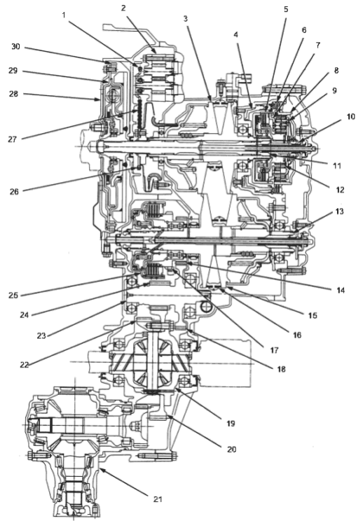
- 1. ATF PUMP DRIVEN SPROCKET
- 2. ATF PUMP
- 3. DRIVE PULLEY
- 4. REVERSE BRAKE PISTON
- 5. FORWARD CLUTCH
- 6. REVERSE BRAKE
- 7. CARRIER
- 8. RING GEAR
- 9. PLANETARY PINION GEAR
- 10. INPUT SHAFT
- 11. DRIVE PULLEY SHAFT
- 12. SUN GEAR
- 13. DRIVEN PULLEY SHAFT
- 14. SECONDARY DRIVE GEAR
- 15. DRIVEN PULLEY
- 16. STEEL BELT
- 17. PARKING GEAR
- 18. SECONDARY DRIVEN GEAR
- 19. DIFFERENTIAL ASSEMBLY
- 20. FINAL DRIVEN GEAR
- 21. TRANSFER ASSEMBLY,
(4WD model) - 22. TRANSFER SHAFT DRIVE GEAR, (4WD model)
- 23. SECONDARY GEAR SHAFT
- 24. FINAL DRIVE GEAR
- 25. START CLUTCH
- 26. ATF PUMP DRIVE SPROCKET
- 27. ATF PUMP DRIVE CHAIN
- 28. DRIVE PLATE
- 29. FLYWHEEL
- 30. RING GEAR
NOTE: The illustration shows the 4WD automatic transmission (sectional view); the 2WD transmission does not have a transfer assembly and transfer shaft drive gear on the differential assembly.
PDF p. 563 · 14-8
Power Flow
N Position
- Start Clutch: released
- Forward Clutch: released
- Reverse Brake: released
Hydraulic pressure is not applied to the start clutch, forward clutch and the reverse brake. Power is not transmitted to the secondary drive gear.
P Position
- Start Clutch: released
- Forward Clutch: released
- Reverse Brake: released
Hydraulic pressure is not applied to the start clutch, forward clutch and the reverse brake. Power is not transmitted to the secondary drive gear. The secondary drive gear is locked by the parking brake pawl interlocking the parking gear.
NOTE: The illustration shows the 4WD automatic transmission, power flow of the 2WD transmission is identical to the 4WD except for parts related to the transfer assembly.
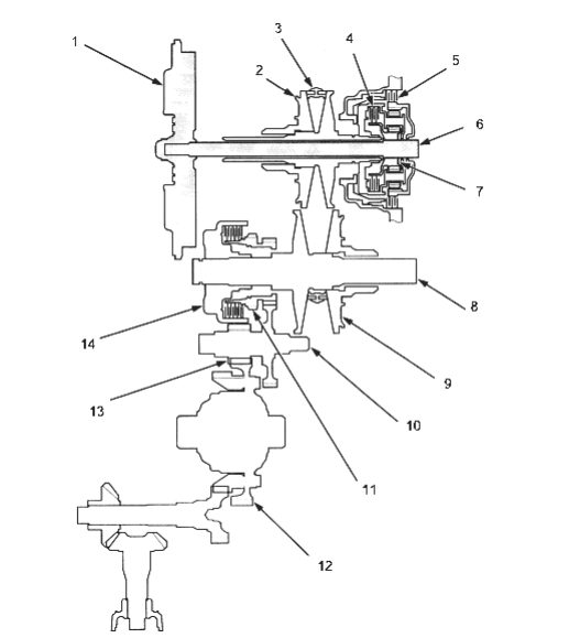
- 1. FLYWHEEL
- 2. DRIVE PULLEY
- 3. STEEL BELT
- 4. FORWARD CLUTCH
- 5. REVERSE BRAKE
- 6. INPUT SHAFT
- 7. SUN GEAR
- 8. DRIVE PULLEY SHAFT
- 9. DRIVEN PULLEY
- 10. SECONDARY DRIVE GEAR
- 11. PARKING GEAR
- 12. FINAL DRIVEN GEAR
- 13. FINAL DRIVE GEAR
- 14. START CLUTCH
.
PDF p. 564 · 14-9
D and L Positions (Forward Range)
- Start Clutch: engaged
- Forward Clutch: engaged
- Reverse Brake: released
- 1.The hydraulic pressure is applied to the forward clutch and the start clutch and the sun gear drives the forward clutch.
- 2.The forward clutch drives the drive pulley shaft, which drives the driven pulley shaft linked by the steel belt.
- 3.The driven pulley shaft drives the secondary drive gear, via the start clutch.
- 4.Power is transmitted to the secondary driven gear, which drives the final driven gear.
NOTE:
- The working hydraulic pressure on the movable face of each shaft depends on the throttle opening position.
- The illustration shows the 4WD automatic transmission, power flow of the 2WD transmission is identical to the 4WD except for parts related to the transfer assembly.
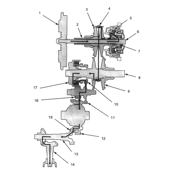
- 1. FLYWHEEL
- 2. DRIVE PULLEY SHAFT
- 3. DRIVE PULLEY
- 4. STEEL BELT
- 5. FORWARD CLUTCH
- 6. INPUT SHAFT
- 7. SUN GEAR
- 8. DRIVE PULLEY SHAFT
- 9. DRIVEN PULLEY
- 10. SECONDARY DRIVE GEAR
- 11. SECONDARY DRIVEN GEAR
- 12. FINAL DRIVEN GEAR
- 13. TRANSFER SHAFT
- 14. TRANSFER DRIVEN GEAR SHAFT
- 15. TRANSFER SHAFT DRIVE GEAR
- 16. FINAL DRIVE GEAR
- 17. START CLUTCH
PDF p. 565 · 14-10
R Position
- Start Clutch: engaged
- Forward Clutch: engaged
- Reverse Brake: released
- 1.The hydraulic pressure is applied to the reverse brake and the start clutch. The sun gear drives gears and the pinion gears revolve around the sun gear. The carrier assembly rotates in the opposite direction from the rotation direction of the sun gear.
- 2.The carrier assembly drives the drive pulley shaft via the forward clutch drum and the drive pulley shaft drives the driven pulley shaft linked by the steel belt.
- 3.The driven pulley shaft drives the secondary drive gear via the start clutch.
- 4.Power is transmitted to the secondary driven gear, which drives the final driven gear.
NOTE: The illustrations shows the 4WD automatic transmission, power flow of the 2WD transmission is identical to the 4WD except for parts related to the transfer assembly.
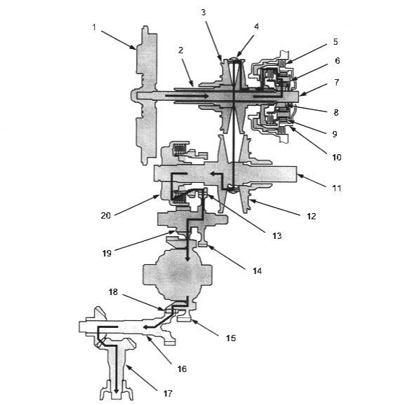
- 1. FLYWHEEL
- 2. DRIVE PULLEY SHAFT
- 3. DRIVE PULLEY
- 4. STEEL BELT
- 5. REVERSE BRAKE
- 6. CARRIER ASSEMBLY
- 7. INPUT SHAFT
- 8. SUN GEAR
- 9. PINION GEAR
- 10. RING GEAR
- 11. DRIVEN PULLEY SHAFT
- 12. DRIVEN PULLEY
- 13. SECONDARY DRIVE GEAR
- 14. SECONDARY DRIVEN GEAR
- 15. FINAL DRIVEN GEAR
- 16. TRANSFER SHAFT
- 17. TRANSFER DRIVEN GEAR SHAFT
- 18. TRANSFER SHAFT DRIVE GEAR
- 19. FINAL DRIVE GEAR
- 20. START CLUTCH
PDF p. 566 · 14-11
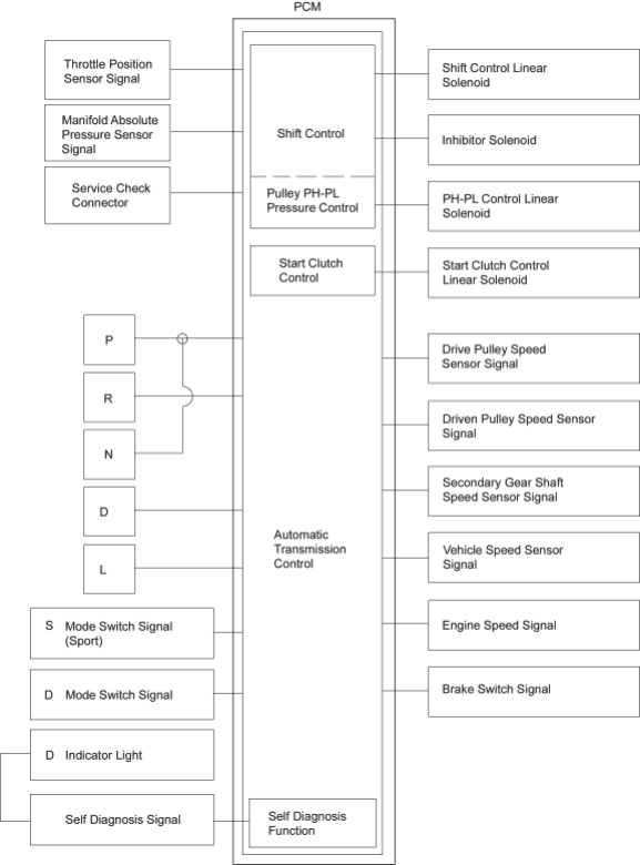
Electronic Control System
The electronic control system consists of a Powertrain Control Module (PCM), sensors, three linear solenoids and an inhibitor solenoid. Shifting is electronically controlled for comfort under all conditions. Also a Grade Logic Control System has been adopted to control shifting in D position while the vehicle is ascending or descending a slope. The PCM is located below the dashboard, under the kick panel on the passenger’s side.
The PCM controls the transmission in such a way as to reduce the engine speed to retain the engine’s cooling efficiency when the car is driven with full throttle acceleration.
If the vehicle is driven with full throttle acceleration continuously, the PCM regulates the pulley hydraulic press to increase the pulley ration, which, as a result, reduces the engine speed and retains the designed cooling efficiency. After the car has been driven with lower engine speed for a while, the PCM increases the pulley ratio to the original ratio.
The start clutch functions to make smooth starting-off possible. Also it generates the creep the same as with the conventional automatic transmissions. The function of the start clutch and the creep in the D, L and R positions is controlled by the clutch hydraulic pressure and the clutch hydraulic pressure is electronically controlled by the PCM. To let the start clutch function appropriately, the PCM regulates the start clutch hydraulic pressure based on the engine’s negative pressure memorised in the N position.
PDF p. 567 · 14-12
Start Clutch Function
The start clutch generates two types of creep, that is weak creep and strong creep, under the following conditions.
Conditions of weak creep:
D position (includes Sport mode), Brake ON and stopped, Throttle OFF, Engine Coolant Temperature above 75°C (167°F).
Conditions of strong creep:
Other conditions than those of weak creep in D position.
Grade Logic Control System
How it works:
The PCM compares actual driving conditions with memorised driving conditions, based on the input from the vehicle speed sensor, the throttle position sensor, the manifold absolute pressure sensor, the engine coolant temperature sensor, the brake switch signal and the shift lever position signal, to control shifting while the vehicle is ascending or descending a slope.
Ascending Control
When the PCM determines that the vehicle is climbing a hill in D position, the system selects the most suitable shift schedule (pulley ratio) according to the magnitude of a gradient, so the vehicle can run smooth and have more power when needed. There are three ascending modes with different shift schedules according to the magnitude of a gradient in the PCM.
Descending Control
When the PCM determines that the vehicle is going down a hill in D position, the system selects the most suitable shift schedule (pulley ratio) according to the magnitude of a gradient. This, in combination with engine braking, achieves smooth driving when the vehicle is descending. There are three descending modes with different shift schedules according to the magnitude of a gradient in the PCM.
PDF p. 568 · 14-13
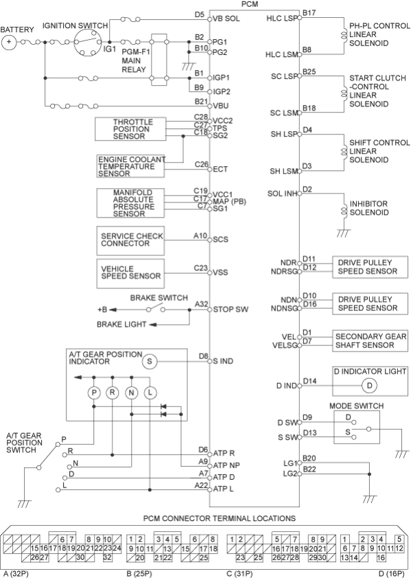
Circuit Diagram and Terminal Locations
PDF p. 569 · 14-14
Hydraulic Control
The hydraulic control system is controlled by the ATF pump, the valves and the solenoids. The ATF pump is driven by the input shaft. The ATF pump and the input shaft are linked by the ATF pump drive chain and the sprockets. The inhibitor solenoid valve and the linear solenoids, which are located on their valve body, are controlled by the PCM. Fluid from the ATF pump flows through the PH regulator valve to maintain specified pressure to the drive pulley, the driven pulley and the manual valve.
The lower valve body assembly includes the main valve body, the PL regulator valve body, the shift valve body, the start clutch control valve body and the secondary valve body.
The lower valve body assembly includes the main valve body, the PL regulator valve body, the shift valve body, the start clutch control valve body and the secondary valve body.
Main Valve Body
The main valve body contains the PH control valve, the lubrication valve and the pitot regulator valve.
PH Control Valve
The PH control valve supplies PH control pressure (PHC) in accordance with the PH-PL control pressure (HLC) and supplies PH control pressure to the PH regulator valve, which also regulates PH pressure. At kick-down, it increases PH control pressure which increases the high (PH) pressure. This shortens the shift speed by releasing the reverse inhibitor pressure (RI) from the inhibitor solenoid valve.
Lubrication Valve
The lubrication valve controls the lubrication pressure to each shaft and maintains lubrication pressure. When the pressure is too high, the spring is compressed. This moves the lubrication valve and opens the fluid leak passage.
Pitot Regulator Valve
The pitot regulator valve controls the start clutch pressure (SC) in accordance with the engine speed, when the electronic control system is faulty.
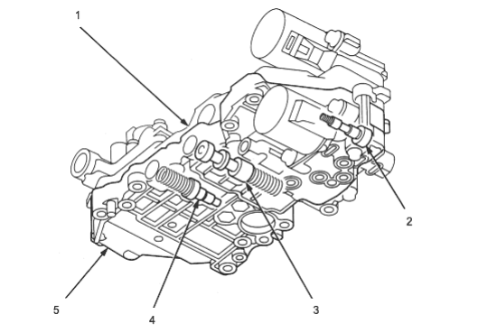
- 1. LOWER VALVE BODY ASSEMBLY
- 2. PITOT REGULATOR VALVE
- 3. LUBRICATION VALVE
- 4. PH CONTROL VALVE
- 5. MAIN VALVE BODY
PDF p. 570 · 14-15
Secondary Valve Body
The secondary valve body contains the PH regulator valve, the clutch reducing valve, the start clutch valve accumulator and the shift inhibitor valve.
PH Regulator Valve
The PH regulator valve maintains hydraulic pressure supplied from the ATF pump and supplies PH pressure to the hydraulic control circuit and the lubrication circuit. PH pressure is regulated at the PH regulator valve by the PH control pressure (PHC) from the PH control valve.
Clutch Reducing Valve
The clutch reducing valve receives PH pressure from the PH regulator valve and regulates the clutch reducing pressure (CR). The clutch reducing valve supplies clutch pressure (CR) to the manual valve and the start clutch control valve and supplies signal pressure to the PH-PL pressure control valve, the shift control valve and the inhibitor solenoid valve.
Start Clutch Valve Accumulator
The start clutch valve accumulator stabilises the hydraulic pressure that is supplied to the clutch.
Shift Inhibitor Valve
The shift inhibitor valve switches the fluid passage to switch the start clutch control from electronic control to hydraulic control when the electronic control system is faulty. It also supplies clutch reducing pressure (CR) to the pitot regulator valve and the pitot lubrication pipe.
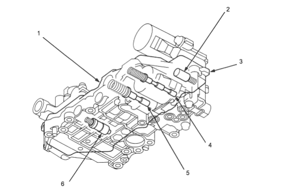
- 1. LOWER VALVE BODY ASSEMBLY
- 2. START CLUTCH VALVE ACCUMULATOR
- 3. SECONDARY VALVE BODY
- 4. SHIFT INHIBITOR VALVE
- 5. CLUTCH REDUCING VALVE
- 6. PH REGULATOR VALVE
PDF p. 571 · 14-16
PL Regulator Valve Body
The PL regulator valve body contains the PL regulator valve and the PH-PL control valve, which is joined with the PH-PL control linear solenoid. The inhibitor solenoid is bolted on the PL regulator valve body.
PL Regulator Valve
The PL regulator valve supplies low pressure (PL) to the pulley to eliminate steel belt slippage.
The PL pressure is controlled by the PH-PL control pressure (HLC).
PH-PL Control Valve
The PH-PL control valve controls the PL regulator valve according to engine torque. The PH-PL control valve supplies PH-PL control pressure (HLC) to the PH control valve to regulate PH pressure higher than PL pressure. The PH-PL control valve is controlled by the PH-PL control linear solenoid, which is controlled by the TCM.
Inhibitor Solenoid
The inhibitor solenoid controls the reverse inhibitor valve by turning on and off. Also, the inhibitor solenoid controls PH control pressure (PHC) by applying reverse inhibitor pressure (R1) to the PH control valve. The inhibitor solenoid is controlled by the PCM.
Start Clutch Control Valve Body
The start clutch control valve body contains the start clutch control valve. Both are joined to the start clutch control linear solenoid.
Start Clutch Control Valve
The start clutch control valve controls start clutch engagement according to the throttle opening. The start clutch control valve is controlled by the start clutch control linear solenoid, which is controlled by the PCM.
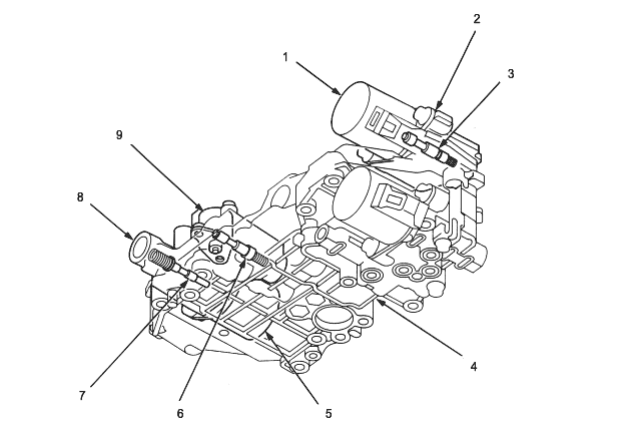
- 1. START CLUTCH CONTROL LINEAR SOLENOID
- 2. START CLUTCH CONTROL VALVE BODY
- 3. START CLUTCH CONTROL VALVE
- 4. LOWER VALVE BODY ASSEMBLY
- 5. PH-PL CONTROL LINEAR SOLENOID
- 6. PL REGULATOR VALVE
- 7. PH-PL CONTROL VALVE
- 8. PL REGULATOR VALVE BODY
- 9. INHIBITOR SOLENOID
PDF p. 572 · 14-17
Shift Valve Body
The shift valve body contains the shift valve and the shift control valve. Both are joined to the shift control linear solenoid.
Shift Valve
The shift valve is controlled by shift valve pressure (SV) from the shift control valve. The shift valve distributes PH pressure and PL pressure to drive pulley and the driven pulley, to shift the transmission.
Shift Control Valve
The shift control valve controls the shift valve in accordance with the throttle opening and vehicle speed. The shift control valve is controlled by the shift control linear solenoid, which is controlled by the TCM. When the electronic control system is faulty, the shift control valve switches the shift inhibitor valve to uncover the port leading the pitot regulator pressure to the start clutch
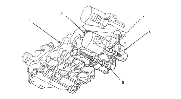
- 1. LOWER VALVE BODY ASSEMBLY
- 2. SHIFT CONTROL LINEAR SOLENOID
- 3. SHIFT CONTROL VALVE
- 4. SHIFT VALVE BODY
- 5. SHIFT VALVE
Manual Valve Body
The manual valve body contains the manual valve and the reverse inhibitor valve. The manual valve body is bolted to the intermediate housing.
Manual Valve
The manual valve mechanically uncovers/covers the fluid passage according to the shift lever position.
Reverse Inhibitor Valve
The reverse inhibitor valve is controlled by the reverse inhibitor pressure (RI). It intercepts the hydraulic circuit to the reverse brake while the vehicle is moving forward at speeds over approximately 6 mph (10 km/h),
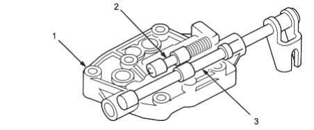
- 1. MANUAL VALVE BODY
- 2. REVERSE INHIBITOR VALVE
- 3. MANUAL VALVE
PDF p. 573 · 14-18
General Chart of Hydraulic Pressure
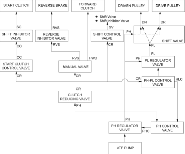
| No | DESCRIPTION OF PRESSURE | No | DESCRIPTION OF PRESSURE |
|---|---|---|---|
| CC | CLUTCH CONTROL | PP | PITOT PIPE |
| COL | ATF COOLER | PR | PITOT REGULATOR |
| CR | CLUTCH REDUCING | RCC | RECIRCULATION |
| DN | DRIVEN PULLEY | RI | REVERSE INHIBITOR |
| DR | DRIVE PULLEY | RVS | REVERSE BRAKE |
| FWD | FORWARD CLUTCH | SC | START CLUTCH |
| HLC | PH-PL CONTROL | SI | SHIFT INHIBITOR |
| LUB | LUBRICATION | SUC | SUCTION |
| PH | PRESSURE HIGH | SV | SHIFT VALVE |
| PHC | PH CONTROL | X | LEAK |
| PL | PRESSURE LOW |
PDF p. 574 · 14-19
Hydraulic Flow
N Position
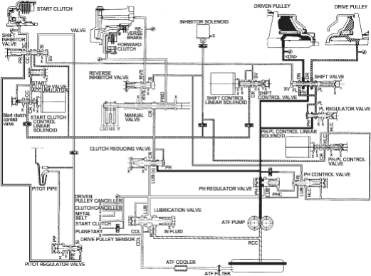
As the engine turns, the ATF pump also starts to operate. Fluid from the ATF pump flows to the PH regulator valve and the clutch reducing valve. The PH regulator valve regulates high pressure (PH) and sends it to the shift valve and the PL regulator valve. The high pressure (PH) flows to the movable face of the driven pulley via the shift valve and turns into low pressure (PL) at the PL regulator valve. The low pressure (PL) flows to the movable face of the drive pulley via the shift valve. At this time, the pulley ratio remains low.
The high pressure (PH) becomes the clutch reducing pressure (CR) at the clutch reducing valve. The clutch reducing pressure (CR) flows to the start clutch control valve, the manual valve, the PH-PL control valve and the shift control valve and is intercepted by those valves.
Under this condition, hydraulic pressure is not applied to the clutches and reverse brake.
PDF p. 575 · 14-20
D position, at low speed range
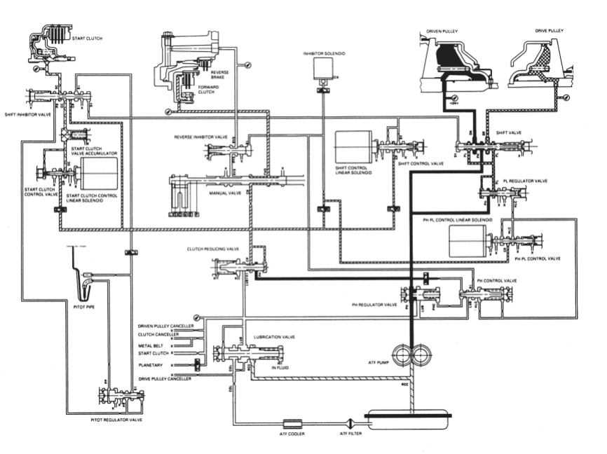
The flow of fluid up to the drive pulley, the driven pulley and the clutch reducing valve is the same as in N position. The pulley ratio is low because the driven pulley receives high pressure (PH) and the drive pulley receives low pressure (PL). The clutch reducing pressure (CR) flows through the manual valve to the forward clutch, then forward clutch is engaged. The forward clutch then drives the drive pulley shaft, which drives the driven pulley shaft.
Also, clutch reducing pressure (CR) becomes start clutch pressure (SC) at the shift inhibitor valve. Start clutch pressure (SC) is applied to the start clutch to engage the start clutch.
PDF p. 576 · 14-21
D position, at middle speed range.
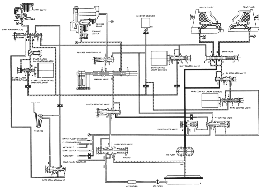
As the speed of the vehicle reaches the prescribed value, the shift control linear solenoid is activated by the PCM. The shift control linear solenoid controls the shift control valve to activate shift valve pressure (SV). Clutch reducing pressure (CR) from the clutch reducing valve becomes shift valve pressure (SV) at the shift control valve. Shift valve pressure (SV) flows to the left end of the shift valve, the shift valve to the right side and positioning it in the middle of its travel. The shift valve covers the port to stop high pressure (PH) to the pulleys and uncovers the port leading low pressure (PL) to the pulleys. The drive pulley and the driven pulley receive low pressure (PL). A this time, the pulley ratio is in the middle.
Pressure remains to apply the forward clutch and the start clutch.
NOTE: When used, “left” or “right” indicates direction on the hydraulic circuit.
PDF p. 577 · 14-22
D position, at high speed range
As the speed of the vehicle reaches the prescribed value, the shift control linear solenoid moves the shift control valve to increase shift valve pressure (SV) at the left end of the shift valve. The shift valve moves to the right side compared to its position at the middle pulley ratio. The shift valve uncovers the port leading high pressure (PH) to the drive pulley and uncovers the port leading low pressure (PL) to the driven pulley. The drive pulley receives high pressure (PH) and the driven pulley receives low pressure (PL). The pulley ratio is high. Pressure remains to apply the forward clutch and the start clutch.
NOTE: When used, “left” or “right” indicates direction on the hydraulic circuit.
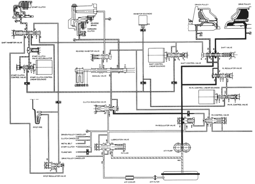
PDF p. 578 · 14-23
R position
The flow of fluid up to the drive pulley, the driven pulley and the clutch reducing valve is the same as in N position. The pulley ratio is low because the driven pulley receives high pressure (PH) and the drive pulley receives low pressure (PL). The manual valve is shifted into the R position and it uncovers the port that leads reverse brake pressure (RVS) to the reverse inhibitor valve. The inhibitor solenoid turns off by means of the PCM and reverse inhibitor pressure (RI) is applied to the right end of the reverse inhibitor valve. The reverse inhibitor valve moves to the left side and uncovers the port that leads reverse brake pressure (RVS) to the reverse brake. Clutch reducing pressure (CR) becomes reverse brake pressure (RVS) at the manual valve and flows to the reverse brake. The reverse brake is engaged and it locks the ring gear.
NOTE: When used, “left” or “ right” indicates direction on the hydraulic circuit.
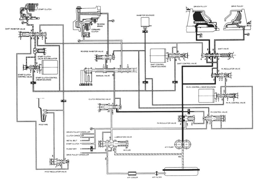
PDF p. 579 · 14-24
R position
Reverse Inhibitor Control
If the D position is selected while the vehicle is moving forward at speeds over 6 mph (10 km/h), the inhibitor solenoid does not turn off by means of the PCM. Reverse inhibitor pressure (RI) is not applied to the reverse inhibitor valve as the reverse inhibitor solenoid turns on. The reverse inhibitor valve is kept on the right side and covers the port to stop reverse brake pressure (RVS) to the reverse brake from the manual valve. Reverse brake pressure (RVS) is not applied to the reverse brake and power is not transmitted to the reverse direction.
NOTE: When used, “left” or “right” indicates direction on the hydraulic circuit.
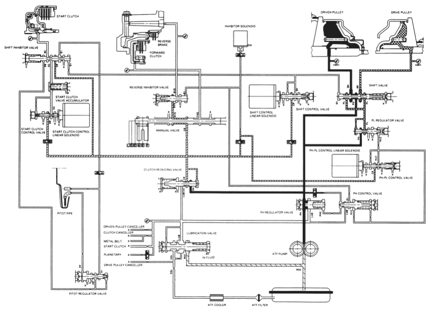
PDF p. 580 · 14-25
P position
The flow of fluid up to the drive pulley, the driven pulley and the clutch reducing valve is the same as in N position. Clutch reducing pressure (CR) flows to the start clutch control valve, the manual valve and the shift control valve and is intercepted by those valves.
Under this condition, hydraulic pressure is not applied to the clutches and reverse brake.
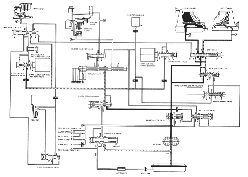
PDF p. 581 · 14-26
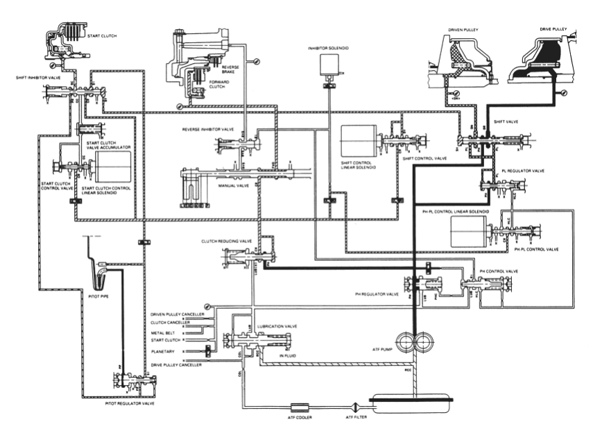
D position, when the electronic control system is faulty.
When the electronic control system (linear solenoids and sensors) is faulty, the transmission uses the pitot pipe pressure (PP) to allow the vehicle to drive.
When all linear solenoids and sensors are off because of a faulty electronic control system, clutch reducing pressure (CR) flows to the start clutch control valve, the manual valve, the PH-PL control valve and the shift control valve. Clutch reducing pressure (CR) becomes shift valve pressure (SV) at the shift control valve and shift valve pressure (SV) is applied to the left end of the shift valve and the right end of the shift inhibitor valve. The shift valve moves to the right side and uncovers the port that leads high pressure (PH) to the drive pulley and uncovers the port that leads low pressure (PL) to the driven pulley. At this time, the pulley ratio is high. The shift inhibitor valve moves to the left side and uncovers the port that leads shift inhibitor pressure (SI) to the pitot lubrication pipe and the pitot regulator valve. The pitot lubrication pipe discharges fluid inside of the pitot flange and discharged fluid enters into the pitot pipe and it is applied to the left end of the pitot regulator valve. The pitot regulator valve moves to the right side and uncovers the port that leads pitot regulator pressure (PR) to the shift inhibitor valve. Pitot regulator pressure (PR) becomes start clutch pressure (SC) at the shift inhibitor valve and is applied to the start clutch. The start clutch is engaged. the forward clutch pressure (FWD) is applied to the forward clutch and the forward clutch is engaged. This allows the vehicle to drive.
NOTE: When used, “left” or “right” indicates direction on the hydraulic circuit.
PDF p. 582 · 14-27
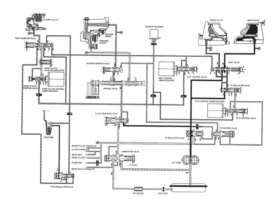
R position, when the electronic control system is faulty
The flow of fluid up to the drive pulley, the driven pulley and the start clutch is the same as in D position. The manual valve is shifted into the R position and it uncovers the port that leads reverse brake pressure (RVS) to the reverse inhibitor valve. Reverse inhibitor pressure (RI) is applied to the right end of the reverse inhibitor valve because of a faulty inhibitor solenoid. The reverse inhibitor valve moves to the left side and uncovers the port that leads reverse brake pressure (RVS) to the reverse brake. Clutch reducing pressure (CR) becomes reverse brake pressure (RVS) at the manual valve and flows to the reverse brake. The reverse brake is engaged and locks the ring gear. This allows the vehicle to drive in reverse.
NOTE: When used, “left” or “right” indicates direction on the hydraulic circuit.
PDF p. 583 · 14-28
Parking Brake Mechanism
The parking brake mechanism locks the transmission by engaging the parking brake pawl with the parking gear which is integral with the secondary drive gear. The secondary drive gear engages with the secondary driven gear which engages with the final driven gear.
Shifting to P position causes the parking cone (installed at the end of the parking brake rod) to press the parking brake pawl onto the parking gear. Even if the end of the parking brake pawl rides on the top of the parking gear teeth, slight movement of the vehicle will cause the parking brake pawl and the parking gear to mesh with each other completely because the parking brake cone receives the tension from the parking brake rod spring. The parking brake pawl receives the tension (which acts to separate the parking brake pawl from the parking gear) from the parking pawl spring.
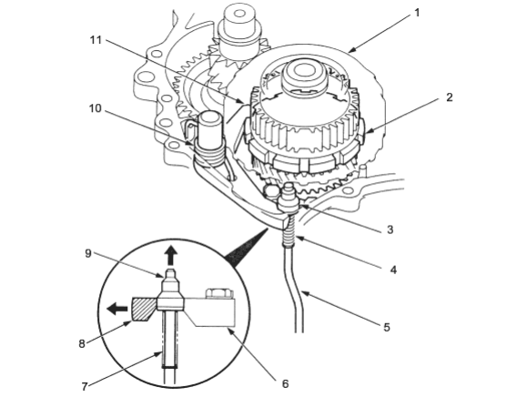
- 1. START CLUTCH
- 2. PARKING GEAR
- 3. PARKING BRAKE CONE
- 4. PARKING BRAKE ROD SPRING
- 5. PARKING BRAKE ROD
- 6. PARKING BRAKE ROD HOLDER
- 7. PARKING BRAKE ROD SPRING
- 8. PARKING BRAKE PAWL
- 9. PARKING BRAKE CONE
- 10. PARKING BRAKE PAWL SPRING
- 11. PARKING BRAKE PAWL
PDF p. 584 · 14-30
Component Locations
LHD:
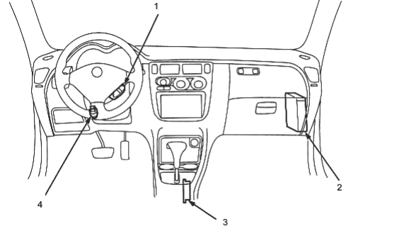
- 1. MODE SWITCH
- 2. POWERTRAIN CONTROL MODULE (PCM)
- 3. AUTOMATIC TRANSAXLE (A/T) GEAR POSITION SWITCH
- 4. BRAKE SWITCH
RHD:
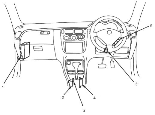
- 1. POWERTRAIN CONTROL MODULE (PCM)
- 2. SHIFT LOCK SOLENOID
(KQ, KU models) - 3. PARKING PIN SWITCH
(KQ, KU models) - 4. AUTOMATIC TRANSAXLE (A/T) GEAR POSITION SWITCH
- 5. BRAKE SWITCH
- 6. MODE SWITCH
PDF p. 585 · 14-31
Engine compartment:
NOTE: LHD model is shown; RHD is similar
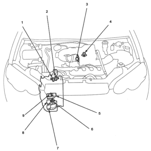
- 1. DRIVEN PULLEY SPEED SENSOR
- 2. SECONDARY GEAR SHAFT SPEED SENSOR
- 3. THROTTLE POSITION (TP) SENSOR
- 4. MANIFOLD ABSOLUTE PRESSURE (MAP) SENSOR
- 5. PH-PL CONTROL LINEAR
SOLENOID - 6. DRIVE PULLEY SPEED SENSOR
- 7. SHIFT CONTROL LINEAR SOLENOID
- 8. START CLUTCH PRESSURE
CONTROL LINEAR SOLENOID - 9. INHIBITOR SOLENOID