PDF p. 550 · 13-76
- 1.Check the two dowel pins are installed in the clutch housing.
- 2.Apply HONDA Genuine Urea Grease UM264 (P/N 41211-PY-305) to the release fork, the release fork bolt, the release bearing and the release bearing guide.
- 3.Install the release bearing, release fork and boot on the transmission.
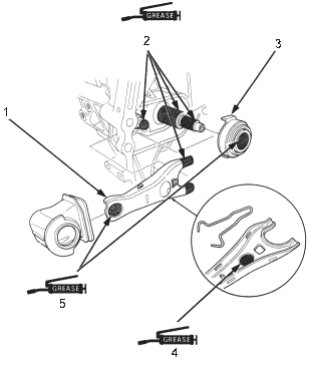
- 1. RELEASE FORK
- 2. GREASE (P/N 41211-PY5-305)
- 3. RELEASE BEARING
- 4. GREASE (P/N 41211-PY5-305), 0.4 - 1.0 g (0.01 - 0.04 oz)
- 5. GREASE (P/N 41211-PY5-305), 0.4 - 1.0 g (0.01 - 0.04 oz)
- 4.Install the starter motor and hose clamp
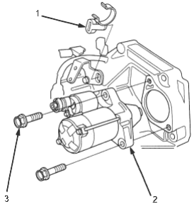
- 1. HOSE CLAMP
- 2. STARTER MOTOR
- 3. 10 x 1.25 mm, 44 Nm (4.5 kgf/m, 32 lbf/ft)
- 5.Place the transmission on the transmission jack and raise it to the engine level.
- 6.Install the two lower transmission mounting bolts.
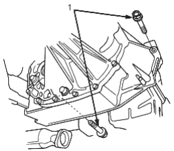
- 1. TRANSMISSION MOUNTING BOLT, 12 x 1.25 mm, 64 Nm (6.5 kgf/m, 47b lbf/ft)
- 7.Raise the transmission, then install the transmission mount bracket and transmission mount rubber.
- Torque the mounting bolts and nuts in the sequence shown.
- Check that the bushings are not twisted or offset.
(1): 12 x 1.25 mm, 64 Nm (6.5 kgf/m, 47 lbf/ft) (2): Temporary tightening
(3): 12 x 1.25 mm, 64 Nm (6.5 kgf/m, 47 lbf/ft) (4): 12 x 1.25 mm, 74 Nm (7.5 kgf/m, 54 lbf/ft)
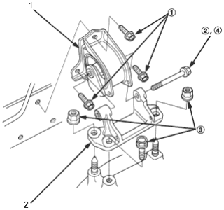
- 1. TRANSMISSION MOUNT RUBBER
- 2. TRANSMISSION MOUNT BRACKET
PDF p. 551 · 13-77
- 8.Install the right front stopper rubber/bracket.
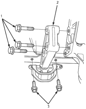
- 1. 12 x 1.25 mm, 64 Nm (6.5 kgf/m, 47 lbf/ft) Replace
- 2. RIGHT FRONT STOPPER RUBBER/BRACKET
- 3. 10 x 1.25 mm, 44 Nm (4.5 kgf/m, 33 lbf/ft)
- 9.Install the clutch cover.
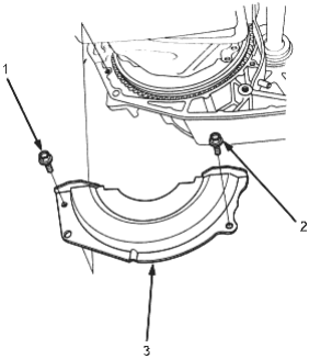
- 1. 6 x 1.0 mm, 9.8 Nm (1.0 kgf/m, 7.2 lbf/ft)
- 2. 8 x 1.25 mm, 24 Nm (2.4 kgf/m, 17 lbf/ft)
- 3. CLUTCH COVER
- 10.Install the engine stiffener.
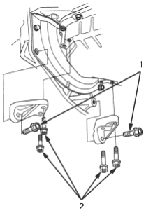
- 1. 10 x 1.25 mm, 44 Nm (4.5 kgf/m, 33 lbf/ft)
- 2. 8 x 1.25 mm, 24 Nm (2.4 kgf/m, 17 lbf/ft)
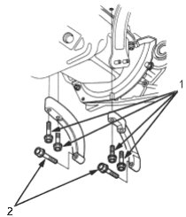
- 1. 8 x 1.25 mm, 24 Nm (2.4 kgf/m, 17 lbf/ft)
- 2. 10 x 1.25 mm, 44 Nm (4.5 kgf/m, 33 lbf/ft)
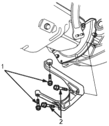
- 1. 8 x 1.25 mm, 24 Nm (2.4 kgf/m, 17 lbf/ft)
- 2. 10 x 1.25 mm, 44 Nm (4.5 kgf/m, 33 lbf/ft)
PDF p. 552 · 13-78
- 11.Install the propeller shaft to the transfer assembly by aligning the reference marks (only SEPM model manual transmission).
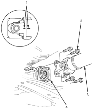
- 1. REFERENCE MARKS
- 2. 8 x 1.25 mm, 32 Nm (3.3 kgf/m, 24lbf/ft)
- 3. PROPELLER SHAFT
- 4. TRANSFER
- 12.Install the rear engine mount bracket/rubber to clutch housing.
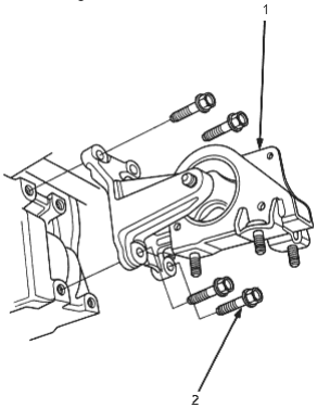
- 1. REAR ENGINE MOUNT BRACKET/RUBBER
- 2. 10 x 1.25 mm, 54 Nm (5.5 kgf/m, 40 lbf/ft)
- 13.Install the rear beam.
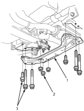
- 1. REAR BEAM
- 2. 10 x 1.25 mm, 38 Nm (3.9 kgf/m, 28 lbf/ft)
- 3. 12 x 1.25 mm, 64 Nm (6.5 kgf/m, 47 lbf/ft)
- 14.Install the exhaust pipe A.
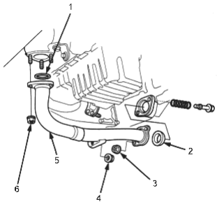
- 1. GASKET, Replace
- 2. GASKET, Replace
- 3. SELF-LOCKING NUT, 8 x 1.25 mm, 22 Nm (2.2 kgf/m, 16 lbf/ft) Replace
- 4. SELF-LOCKING NUT, 8 x 1.25 mm, 16 Nm (1.6 kgf/m, 12 lbf/ft) Replace
- 5. EXHAUST PIPE A
- 6. SELF-LOCKING NUT, 10 x 1.25 mm, 54 Nm (5.5 kgf/m, 40 lbf/ft) Replace
PDF p. 553 · 13-79
- 15.Install the intermediate shaft (see section 16).
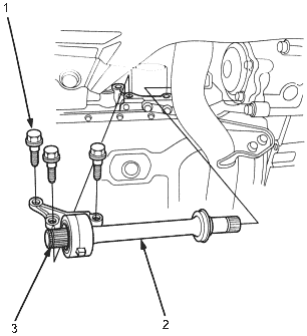
- 1. 10 x 1.25 mm, 39 Nm (4.0 kgf/m, 29 lbf/ft)
- 2. INTERMEDIATE SHAFT
- 3. SE RING, Replace
- 16.Install the driveshafts with new set rings (see section 16).
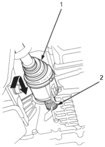
- 1. DRIVESHAFT
- 2. SET RING, Replace
- 17.Install the knuckle onto the lower arms and install the castle nuts and lock pins (see section 18).
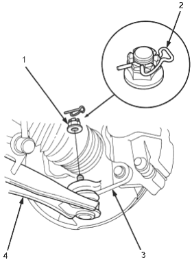
- 1. CASTLE NUT, 12 x 1.25 mm, 45 - 59 Nm (5.0 - 6.0 kgf/m, 36 - 43 lbf/ft)
- 2. LOCK PIN, Replace
- 3. KNUCKLE
- 4. LOWER ARM
- 18.Connect the from stabiliser link and front stabiliser, then hold the stabiliser link ball joint pin with a hexagonal wrench and tighten the flange nut.
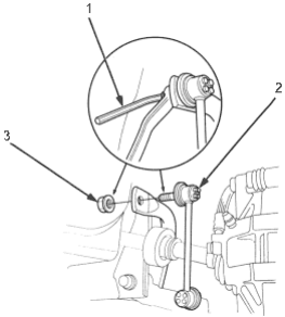
- 1. HEXAGONAL WRENCH
- 2. FRONT STABILISER LINK
- 3. 10 x 1.25 mm, 29 Nm (3.0 kgf/m, 22 lbf/ft)
PDF p. 554 · 13-80
- 19.Install the splash shield.
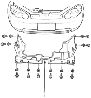
- 1. SPLASH SHIELD
- 20.Install the three upper transmission mounting bolts.
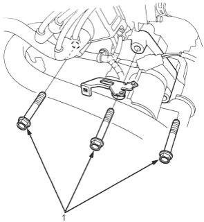
- 1. 12 x 1.25 mm, 64 Nm (6.5 kgf/m, 47 lbf/ft)
- 21.Connect the vehicle speed sensor (VSS) connector.
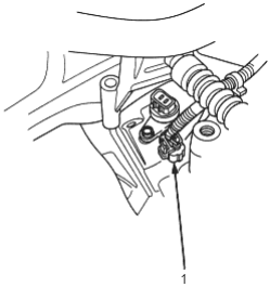
- 1. VSS CONNECTOR
- 22.Install the cable bracket and cables. turn the shift lever boot so the hole is facing down.
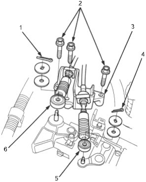
- 1. COTTER PIN, Replace
- 2. 8 x 1.25 mm, 27 Nm (2.8 kgf/m, 20 lbf/ft)
- 3. CABLE BRACKET
- 4. COTTER PIN, Replace
- 5. SELECT CABLE
- 6. SHIFT CABLE
PDF p. 555 · 13-81
- 23.Connect the back-up light switch connector.
- 24.Install the wire harness clamp.
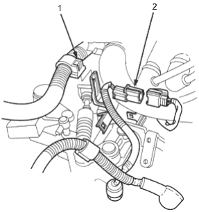
- 1. HARNESS CLAMP
- 2. BACK-UP LIGHT SWITCH CONNECTOR
- 25.Connect the starter motor cables and transmission ground cable. make sure that the crimped side of the ring terminal is facing out.
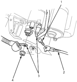
- 1. 6 x 1.0 mm, 9.8 Nm (1.0 kgf/m, 7.2 lbf/ft)
- 2. TRANSMISSION GROUND CABLE
- 3. STARTER MOTOR CABLES
- 4. 6 x 1.0 mm, 9.8 Nm (1.0 kgf/m, 7.2 lbf/ft)
- 26.Apply HONDA Genuine Urea Grease UM264 (P/N 41211-PY5-305) to the end of the slave cylinder rod. Install the slave cylinder and clutch line clamp. Take care not to bend the clutch line.
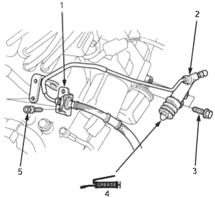
- 1. CLUTCH HOSE BRACKET
- 2. SLAVE CYLINDER
- 3. 8 x 1.25 mm, 22 Nm (2.2 kgf/m, 16 lbf/ft)
- 4. GREASE (P/N 41211-PY5-305)
- 5. 6 x 1.0 mm, 9.8 NM (1.0 kgf/m, 7.2 lbf/ft)
- 27.Turn the breather cap so that the “F” mark points towards the front of the vehicle.
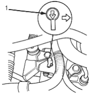
- 1. BREATHER CAP
- 28.Install the battery. Connect the positive (+) cable first, then the negative (-) cable to the battery.
- 29.Refill the MTF (See page 13-4).
- 30.Test drive the vehicle.
- 31.Check the clutch operation.
- 32.Check the transmission for noise and smooth operation.
- 33.Check the front wheel alignment (see section 18).