PDF p. 497 · 13-24
- 1.
Measure the clearances between the reverse shift holder and 5th/reverse shift piece pin.
Standard: A: 0.05 - 0.35 mm (0.002 - 0.014 in)
B: 0.4 - 0.8 mm (0.02 - 0.03 in) Service Limit: A: 0.5 mm (0.02 in)
B: 1.0 mm (0.04 in)
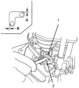
- 1. REVERSE SHIFT HOLDER
- 2. 5TH/REVERSE SHIFT PIECE PIN
- 2.
If the clearances are more than the service limit, measure the widths of the groove in the reverse shift holder.
Standard: A: 7.05 - 7.25 mm (0.278 - 0.285 in)
B: 7.4 - 7.7 mm (0.29 - 0.30 in)
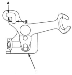
- 1. REVERSE SHIFT HOLDER
- If the widths of the grooves are not within the standard, replace the reverse shift holder with a new one.
- If the widths of the grooves are within the standard, replace the 5th/reverse shift piece with a new one.
- 3.
Measure the clearance between the reverse idler gear and reverse shift holder.
Standard: 0.5 - 1.1 mm (0.02 - 0.04 in)
Service Limit: 1.8 mm (0.07 in)
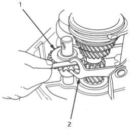
- 1. REVERSE IDLER GEAR
- 2. REVERSE SHIFT HOLDER
- 4.
If the clearance is more than the service limit, measure the width of the reverse shift holder.
Standard: 13.0 - 13.3 mm (0.512 - 0.524 in)
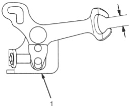
- 1. REVERSE SHIFT HOLDER
- If the width is not within the standard, replace the reverse shift holder with a new one.
- If the width is within the standard, replace the reverse idler gear with a new one.