PDF p. 479 · 13-6
Inspection
- 6.
Set a dial indication on the transfer assembly flange, then measure the transfer gear backlash.
STANDARD: 0.06 - 0.16 MM (0.002 - 0.006 in)
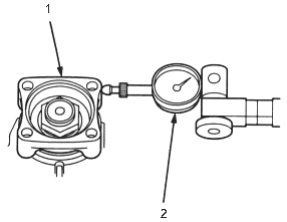
1 COMPANION FLANGE
- 2.DIAL INDICATOR
- 7.If the measurement is out of specification, remove the transfer assembly and adjust transfer gear backlash (See page 13-48) to (See page 13-65).
- 8.Check the transfer oil seal for damage and fluid leaks.
- 9.
If oil seal replacement is required, remove the transfer assembly, replace the oil seal and adjust the total starting torque (See page 13-48) to (See page 13-65).
NOTE: Do not replace the oil seal when the transfer assembly is installed on the transmission.
Removal
- 1.Raise the front of the vehicle and support it with safety stands (see section 1).
- 2.Set the parking brake and block both rear wheels securely.
- 3.Drain the MTF (See page 13-4).
- 4.Remove the exhaust pipe A.
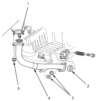
- 1. GASKET, Replace
- 2. GASKET, Replace
- 3. SELF-LOCKING NUT, Replace
- 4. EXHAUST PIPE A
- 5. SELF-LOCKING NUT, Replace
PDF p. 480 · 13-7
- 5.Make reference marks across the propeller shaft and the transfer assembly flanges.
- 6.Separate the propeller shaft from the transfer assembly flanges.
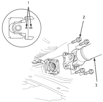
1 REFERENCE MARKS
- 2.8 x 1.25 mm, Replace
- 3.PROPELLER SHAFT
- 7.
Remove the rear stiffener, then remove the transfer assembly.
NOTE: While servicing the transfer assembly, do not allow dust or other foreign particles to enter the transmission.
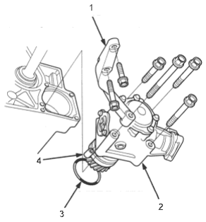
1 REAR STIFFENER
- 2.TRANSFER ASSEMBLY
- 3.O-RING, Replace
- 4.DOWEL PIN
Installation
- 1.Install the new O-ring on the transfer assembly.
- 2.Clean the areas where the transfer assembly contacts the transmission with solvent or carburettor cleaner, and dry with compressed air. Then apply MTF to the contact areas.
- 3.
Install the transfer assembly on the transmission.
NOTE: While installing the transfer assembly on the transmission, do not allow dust or other foreign particles to enter the transmission.
- 4.Install the rear stiffener.
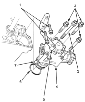
- 1. 8 x 1.25 mm, 24 Nm (2.4 kgf/m, 17 lbf/ft)
- 2. 10 x 1.25 mm, 44 Nm (4.5 kgf/m, 33 lbf/ft)
- 3. 10 x 1.25 mm, 64 Nm (6.5 kgf/m, 47 lbf/ft)
- 4. TRANSFER ASSEMBLY
- 5. REAR STIFFENER
- 6. O-RING, Replace
- 7. DOWEL PIN
PDF p. 481 · 13-8
- 5.Install the propeller shaft to the transfer assembly by aligning the reference marks.
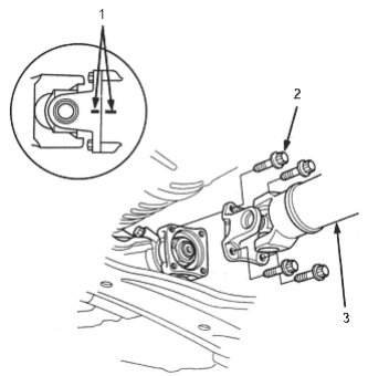
1 REFERENCE MARKS
- 2.8 x 1.25 mm, 32 Nm (3.3 kgf/m, 24 lbf/ft) Replace
- 3.PROPELLER SHAFT
- 7.Install the exhaust pipe A.
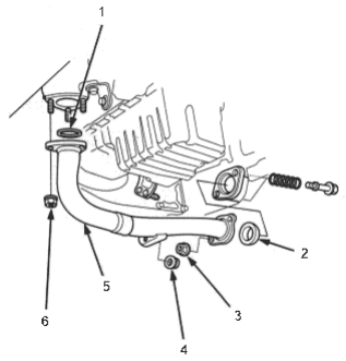
1 GASKET, Replace
- 2.GASKET, Replace
- 3.SELF-LOCKING NUT, 8 x 1.25 mm, 22 Nm (2.2 kgf/m, 16 lbf/ft) Replace
- 4.SELF-LOCKING NUT, 8 x 1.25 mm, 16 Nm (1.6 kgf/m, 12 lbf/ft) Replace
- 5.EXHAUST PIPE A
- 6.SELF-LOCKING NUT, 10 x 1.25 mm, 54 Nm (5.5 kgf/m, 40 lbf/ft) Replace
- 7.Refill the MTF (See page 13-4).
- 8.Start the engine and run it to normal operation temperature (the radiator fan comes on). Turn the engine OFF and check the fluid level.