PDF p. 1837 · 11-56
DTC P0107: Low Voltage in MAP Sensor Circuit
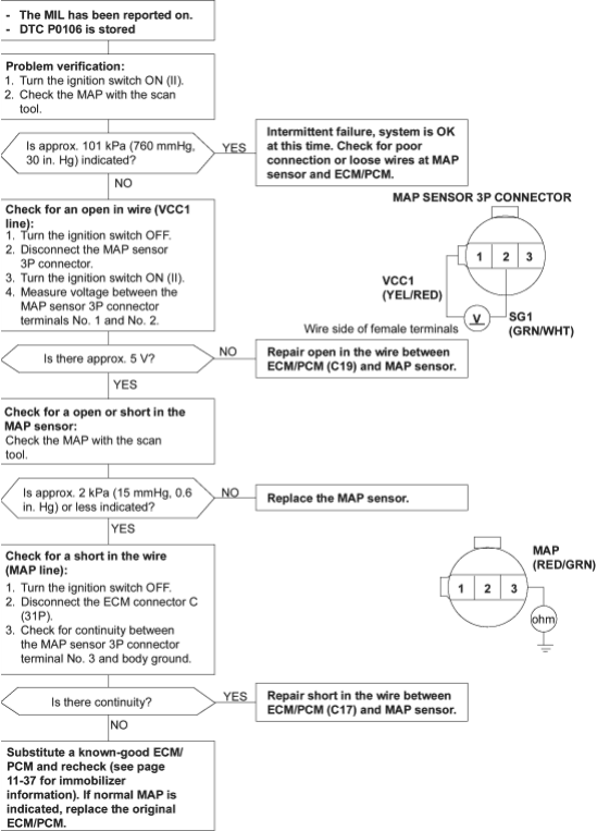
To go to the page referenced on the diagram above, click on the following:
(See Page 11-37)
PDF p. 1838 · 11-57
DTC P0108: High Voltage in MAP Sensor Circuit
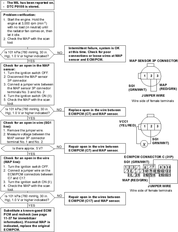
To go to the page referenced on the diagram above, click on the following:
(See Page 11-37)
PDF p. 1839 · 11-58
DTC P0112: Low Voltage in IAT Sensor Circuit
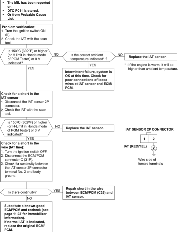
To go to the page referenced on the diagram above, click on the following:
(See Page 11-37)
PDF p. 1840 · 11-59
DTC P0113: High Voltage in IAT Sensor Circuit
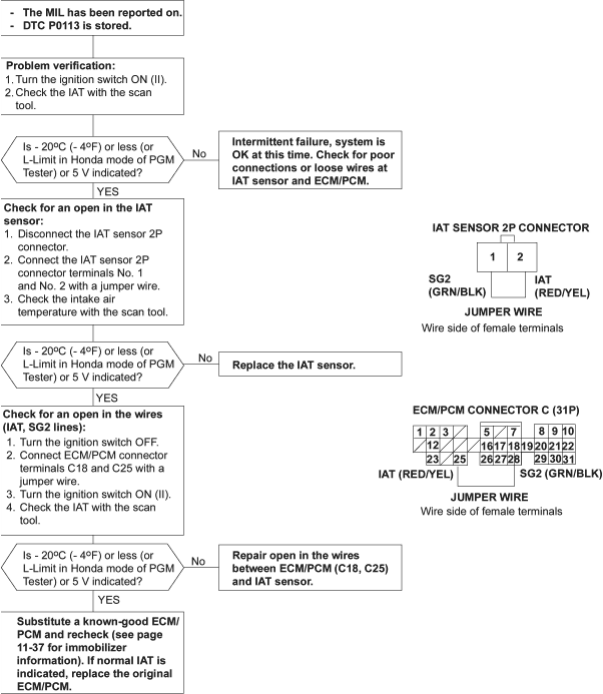
To go to the page referenced on the diagram above, click on the following:
(See Page 11-37)
PDF p. 1841 · 11-60
DTC P0117: Low Voltage in ECT Sensor Circuit
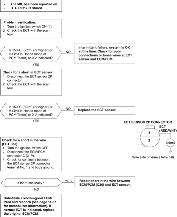
To go to the page referenced on the diagram above, click on the following:
(See Page 11-37)
PDF p. 1842 · 11-61
DTC P0118: High Voltage in ECT Sensor Circuit
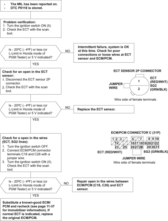
To go to the page referenced on the diagram above, click on the following:
(See Page 11-37)
PDF p. 1843 · 11-62
DTC P0122: Low Voltage in TP Sensor Circuit
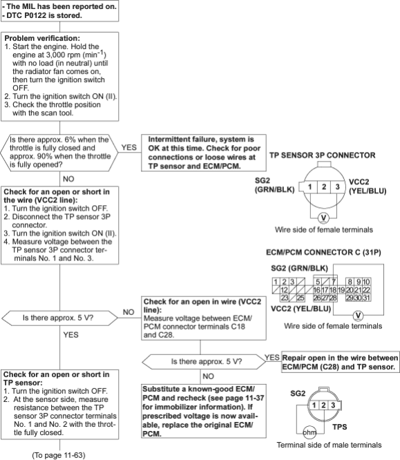
To go to the page referenced on the diagram above, click on the following:
(See Page 11-37)
PDF p. 1844 · 11-63
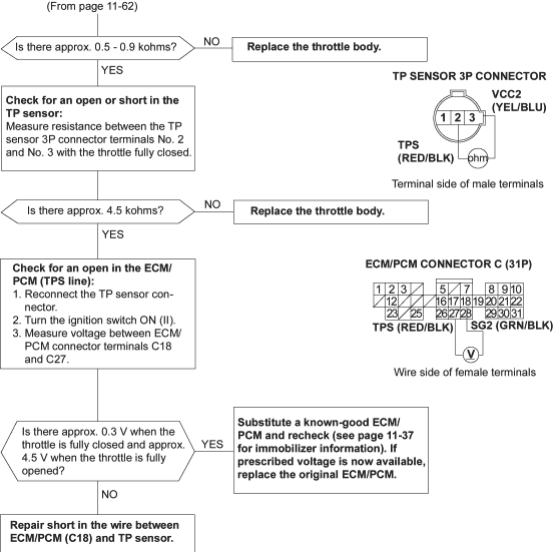
To go to the page referenced on the diagram above, click on the following:
(See Page 11-37)
PDF p. 1845 · 11-64
DTC P0123: High Voltage in TP Sensor Circuit
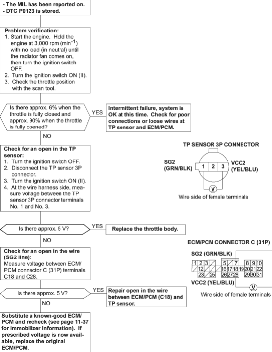
To go to the page referenced on the diagram above, click on the following:
(See Page 11-37)
PDF p. 1846 · 11-65
DTC P0131: Low Voltage in Primary HO2S (Sensor 1) Circuit
NOTE: Lack of fuel may cause DTC P0131.
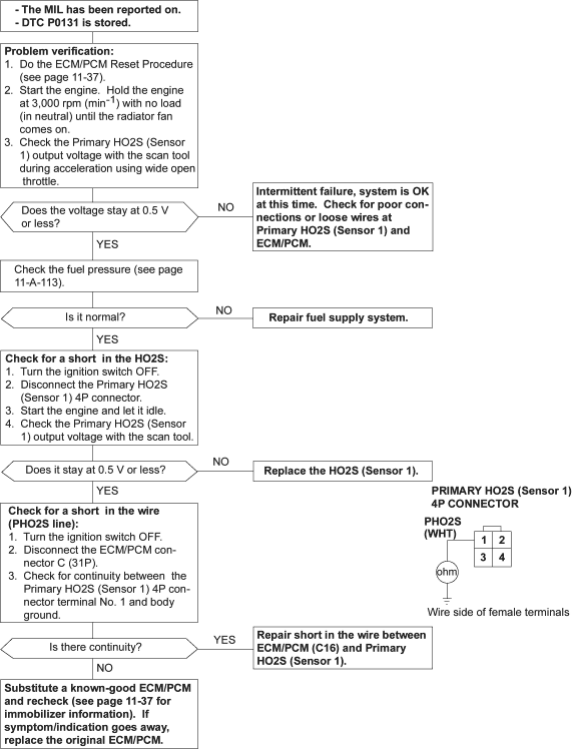
To go to the page referenced on the diagram above, click on the following:
(See Page 11-37)
PDF p. 1847 · 11-66
DTC P0132: High Voltage in Primary HO2S (Sensor 1) Circuit
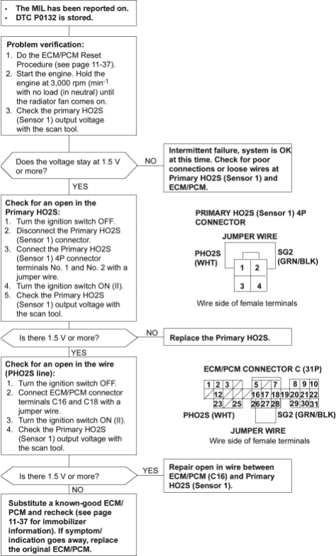
To go to the page referenced on the diagram above, click on the following:
(See Page 11-37)
PDF p. 1848 · 11-67
DTC P0133: Slow Response in Primary HO2S (Sensor 1) Circuit
Description
By controlling the air/fuel ratio with a Primary HO2S (Sensor 1) and a Secondary HO2S (Sensor 2), the deterioration of the Primary HO2S (Sensor 1) can be evaluated by its feedback period. When the feedback period of the HO2S exceeds a certain value during stable driving conditions, the sensor will be judged as deteriorated.
When deterioration has been detected during two consecutive trips, the MIL comes on and DTC P0133 will be stored.
NOTE: If DTC P0131, P0132 and/or P0135 are stored at the same time as DTC P0133, troubleshoot those DTCs first, then troubleshoot DTC P0133.
Possible Cause
- Primary HO2S (Sensor 1) Deterioration
- Primary HO2S Heater (Sensor 1) Deterioration
- Exhaust System Leakage
Troubleshooting Flowchart
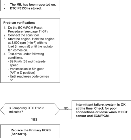
To go to the page referenced on the diagram above, click on the following:
(See Page 11-37)
PDF p. 1849 · 11-68
DTC P0135: Malfunction in primary HO2S (Sensor 1) Heater Circuit DTC P0141: Malfunction in Secondary HO2S (Sensor 2) Heater Circuit
NOTE: Information marked with an asterisk (*) applies to DTC P0141.
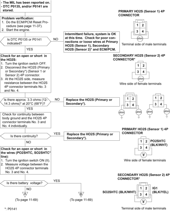
- *:
P0141
To go to the page referenced on the diagram above, click on the following:
(See Page 11-37)
PDF p. 1850 · 11-69
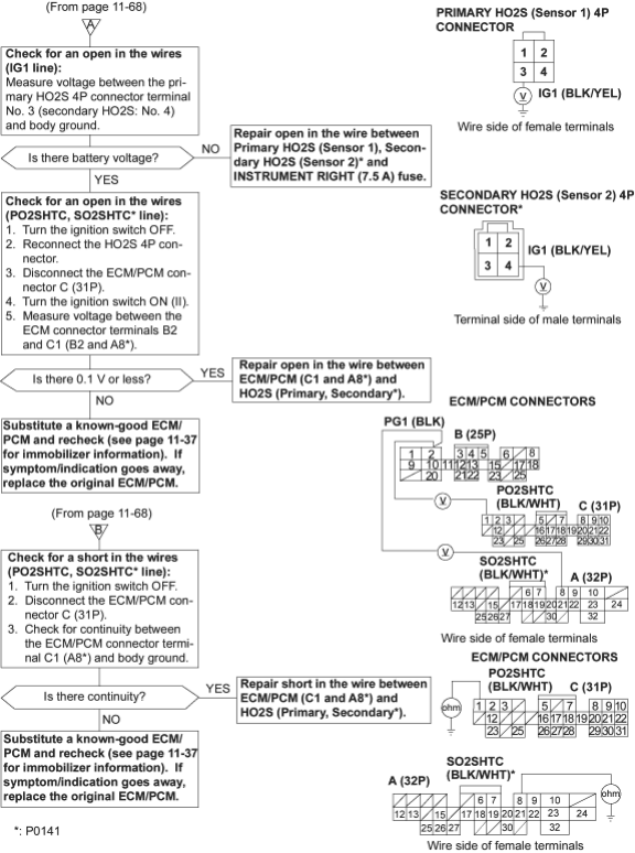
- *:
P0141
To go to the page referenced on the diagram above, click on the following:
(See Page 11-37)
PDF p. 1851 · 11-70
DTC P0137: Low Voltage in Secondary HO2S (Sensor 2) Circuit
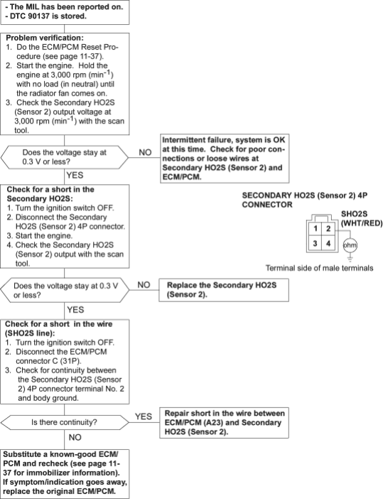
To go to the page referenced on the diagram above, click on the following:
(See Page 11-37)
PDF p. 1852 · 11-71
DTC P0138: High Voltage in Secondary HO2S (Sensor 2) Circuit
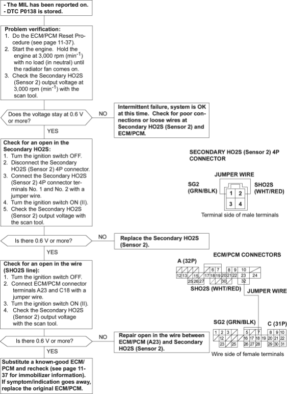
To go to the page referenced on the diagram above, click on the following:
(See Page 11-37)
PDF p. 1853 · 11-72
DTC P0139: Slow Response in the Secondary HO2S (Sensor 2) Circuit
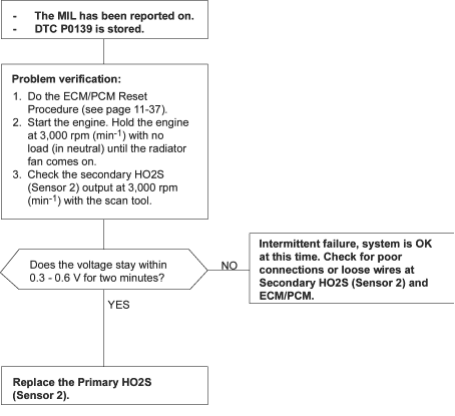
To go to the page referenced on the diagram above, click on the following:
(See Page 11-37)
PDF p. 1854 · 11-73
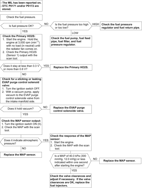
DTC P0171: Fuel System Too Lean
DTC P0172: Fuel System Too Rich
NOTE: If some of the DTCs listed below are stored at the same time as DTC P0171 and/or P0172, troubleshoot those DTCs first, then recheck the system.
- P0107, P0108: MAP sensor
- P0135: Primary HO2S (Sensor 1) Heater
- P0137, P0138: Secondary HO2S (Sensor 2)
- P0141: Secondary HO2S (Sensor 2) Heater
- P0443: EVAP Purge Control Solenoid Valve Circuit
Possible Cause
DTC P0171
System too lean
- Fuel Pump insufficient flow/pressure
- Fuel Feed Line clogged, leaking
- Fuel Pressure Regulator stuck open
- Fuel Filter clogged
- Fuel Injector clogged, air inclusion
- Gasoline doesn’t meet Owner’s Manual spec.
- Primary HO2S (Sensor 1) deteriorated
- MAP Sensor range/performance
- Valve Clearance
- Exhaust leak
DTC P0172 System too rich
- Fuel Pressure Regulator clogged, stuck closed
- Fuel Return Pipe clogged
- Fuel Injector leaking
- Gasoline doesn’t meet Owner’s Manual spec.
- Primary HO2S (Sensor 1) deteriorated
- MAP Sensor range/performance
- EVAP Purge Control Solenoid Valve leaking, stuck open
- Valve Clearance
PDF p. 1855 · 11-74
Troubleshooting Flowchart
PDF p. 1856 · 11-75
DTC P0300: Random misfire and any combination of the following:
DTC P0301: Cylinder 1 misfire
DTC P0302: Cylinder 2 misfire
DTC P0303: Cylinder 3 misfire
DTC P0304: Cylinder 4 misfire
NOTE:
- If the misfiring is frequent enough to trigger detection of increased emissions during two consecutive driving cycles, the MIL will come on, and DTC P0300 (and some combination of P0301 through P0304) will be stored.
- If the misfiring is frequent enough to damage the catalyst, the MIL will blink whenever the misfiring occurs, and DTC P0300 (and some combination of P0301 through P0304) will be stored. When the misfiring stops, the MIL will remain on.
- 1.Troubleshoot the following DTCs first if any of them were stored along with the random misfire DTC (s):
- P0107, P0108: MAP Sensor
- P0131, P0132: Primary HO2S
- P0171, P0172: Fuel Metering
- P1361, P1362: TDC Sensor
- P1381, P1382: CYP Sensor
- P1508: IAC valve (D16W5 engine)
- P1519: IAC Valve (D16W1 engine)
- 2.Test-drive the vehicle to verify the symptom.
- 3.Find the symptom in the chart below, and do the related procedures in the order listed until you find the cause.
| Symptom | Procedure (s) | Also check for: | ||
|---|---|---|---|---|
| Random misfire only at low RPM and load | Check fuel pressure (See Page 11-106). | ♦ | Low compression | |
| ♦ | Low quality fuel | |||
| Random misfire only during acceleration | 1. | Check fuel pressure (See Page 11-106). | Malfunction in the VTEC | |
| 2. | Test the ignition coils (see section 4). | system (see section6)* | ||
| Random misfire only at high RPM and | 1. | Check fuel pressure (See Page 11-106). | Correct value clearance (see | |
| load, or under random conditions | 2. | Test the ignition coils (see section 4). | section 6) | |
- *:
D16W5 engine
NOTE: If misfire doesn’t recur, some possible causes are that the fuel doesn’t meet owner’s manual spec, lack of fuel, carbon deposits on spark plug, etc.
PDF p. 1857 · 11-76
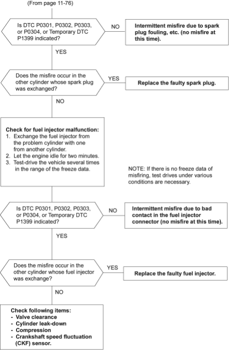
DTC P0301: Cylinder 1 misfire detected
DTC P0302: Cylinder 2 misfire detected
DTC P0303: Cylinder 3 misfire detected
DTC P0304: Cylinder 4 misfire detected
NOTE: If some of the DTCs listed below are stored at the same time as a misfire DTC, troubleshoot those DTCs first, then recheck for the misfire DTC.
- P0131, P0132: Primary HO2S
- P0171, P0172: Fuel Supply System
- P1361, P1362: TDC Sensor
- P1381, P1382: CYP Sensor
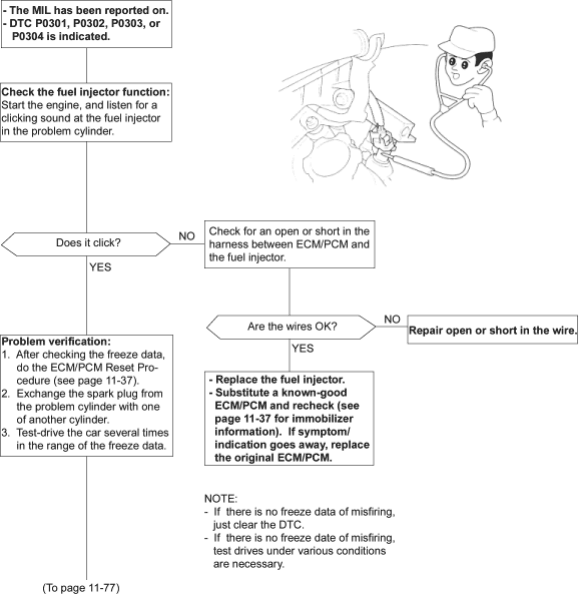
To go to the page referenced on the diagram above, click on the following:
(See Page 11-37)
PDF p. 1858 · 11-77
PDF p. 1859 · 11-78
DTC P0325 (D16W5 engine): Malfunction in Knock Sensor Circuit
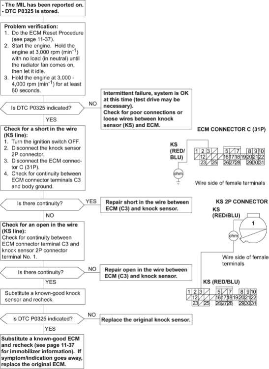
To go to the page referenced on the diagram above, click on the following:
(See Page 11-37)
PDF p. 1860 · 11-79
DTC P0335: Malfunction in CKP Sensor Circuit
DTC P0336: Range/Performance Problem in CKP Sensor Circuit DTC P1361: Intermittent interruption in TDC Sensor Circuit
DTC P1362: No signal in TDC Sensor Circuit
DTC P1381: Intermittent interruption in CYP Sensor Circuit
DTC P1382: No signal in CYP Sensor Circuit
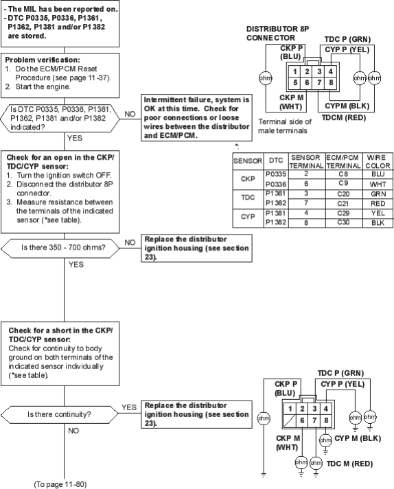
To go to the page referenced on the diagram above, click on the following:
(See Page 11-37)
PDF p. 1861 · 11-80
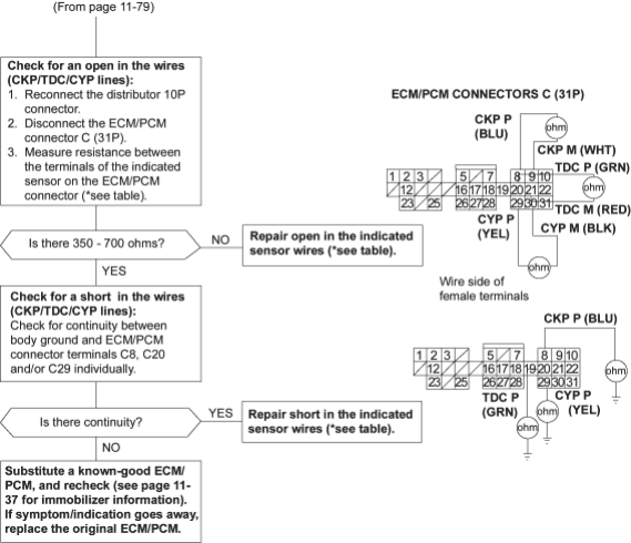
To go to the page referenced on the diagram above, click on the following:
(See Page 11-37)
PDF p. 1862 · 11-81
DTC P0500 (M/T): Malfunction in VSS Circuit DTC P0501 (A/T): Malfunction in VSS Circuit
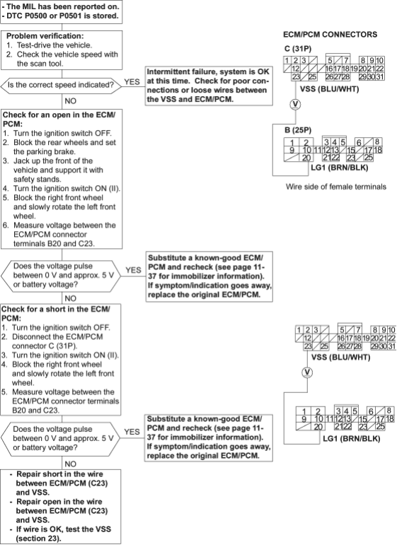
To go to the page referenced on the diagram above, click on the following:
(See Page 11-37)
PDF p. 1863 · 11-82
DTC P1107: Low Voltage in Barometric Pressure (BARO) Sensor Circuit DTC P1108: High Voltage in Barometric Pressure (BARO) Sensor Circuit
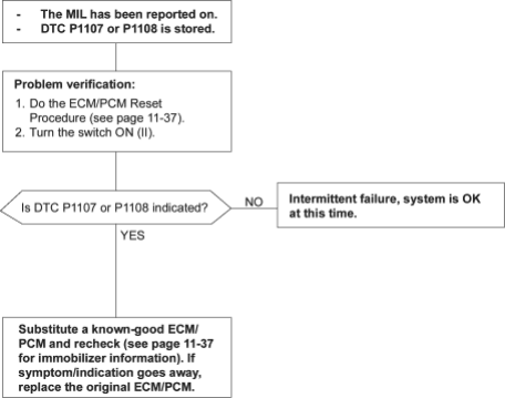
To go to the page referenced on the diagram above, click on the following:
(See Page 11-37)
PDF p. 1864 · 11-83
DTC P1297: Low Voltage in ELD Circuit
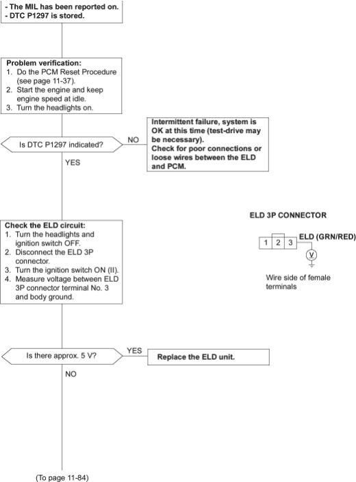
To go to the page referenced on the diagram above, click on the following:
(See Page 11-37)
PDF p. 1865 · 11-84
.
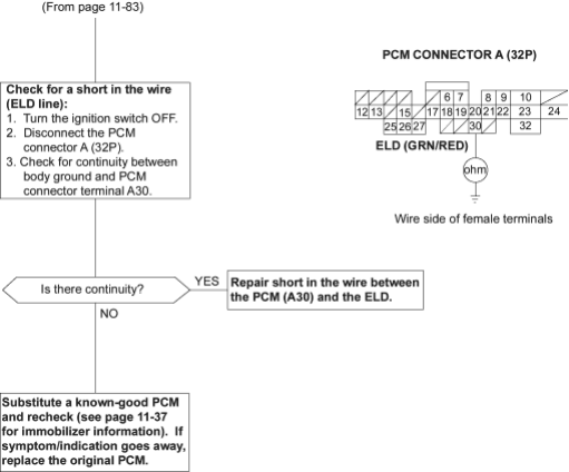
To go to the page referenced on the diagram above, click on the following:
(See Page 11-37)
PDF p. 1866 · 11-85
DTC P1298: High Voltage in ELD Circuit
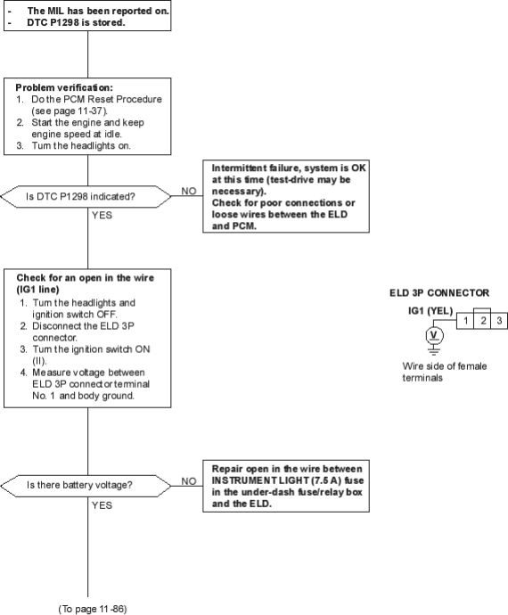
To go to the page referenced on the diagram above, click on the following:
(See Page 11-37)
PDF p. 1867 · 11-86
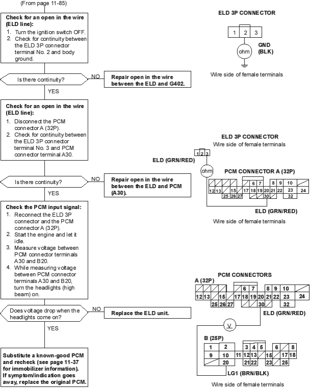
To go to the page referenced on the diagram above, click on the following:
(See Page 11-37)
PDF p. 1868 · 11-87
DTC P1336: Intermittent interruption in CKF Sensor Circuit DTC P1337: No signal in CKF Sensor Circuit
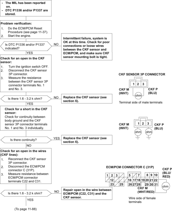
To go to the page referenced on the diagram above, click on the following:
(See Page 11-37)
PDF p. 1869 · 11-88
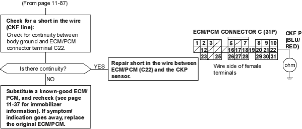
To go to the page referenced on the diagram above, click on the following:
(See Page 11-37)
PDF p. 1870 · 11-89
DTC P1359: Malfunction in CKP/TDC/CYP Sensor Circuit
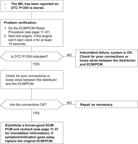
To go to the page referenced on the diagram above, click on the following:
(See Page 11-37)
PDF p. 1871 · 11-90
DTC P1472: Low Voltage in EGT Sensor Circuit DTC P1473: High Voltage in EGT Sensor Circuit
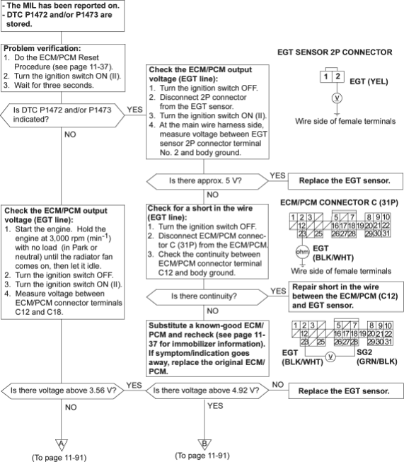
To go to the page referenced on the diagram above, click on the following:
(See Page 11-37)
PDF p. 1872 · 11-91
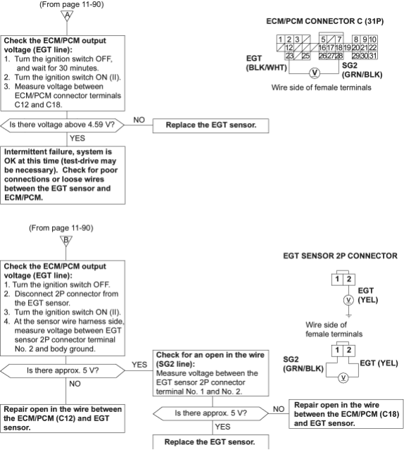
PDF p. 1873 · 11-92
DTC P1607: Malfunction in ECM/PCM Internal Circuit
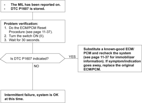
To go to the page referenced on the diagram above, click on the following:
(See Page 11-37)