PDF p. 1834 · 11-53
The programmed Fuel Injection (PGM-FI) system is a sequential multiport fuel injection system.
Fuel Injector Timing and Duration
The ECM/PCM contains the memory for basic discharge duration at various engine speeds and manifold pressures. The basic discharge duration, after being read out from the memory, is further modified by signals sent from various sensors to obtain the final discharge duration. By monitoring Long Term Fuel Trim, the ECM/PCM detects long term malfunctions in the fuel system, and will set a DTC if the malfunction occurs during two consecutive trips.
Ignition Timing Control
The ECM/PCM contains the memory for basic ignition timing at various engine speeds and manifold air flow rates. It also adjusts the timing according to engine coolant temperature. The ECM/PCM detects misfiring by using the CKP sensor to monitor fluctuations in crankshaft speed.
It will then set DTCs depending on how much misfiring occurs.
Starting Control
When the engine is started, the ECM/PCM provides a rich mixture by increasing fuel injector duration.
Alternator Control
The alternator signals the ECM/PCM during charging. The ECM/PCM then controls the voltage generated at the alternator according to the electrical load determined by the ELD (Electrical Load Detector) and driving mode. This reduces engine load to improve fuel economy.
A/C Switch
The A/C (air conditioning) switch signals the ECM/PCM whenever there is a demand for cooling.
A/C Compressor Clutch Relay
When the ECM/PCM receives a demand for cooling from the A/C system, it delays the compressor from being energised, and enriches the mixture to assure smooth transition to the A/C mode.
Vehicle Speed Sensor (VSS)
The speed sensor generates a pulsed signal from an input of 5 volts. The number of pulses per minutes increases/decreases with the speed of the vehicle.
Crankshaft Position (CKP)/Top Dead Centre (TDC)/Cylinder Position (CYP) Sensor
The CKP Sensor determines timing for fuel injection and ignition of each cylinder and also detects engine speed. The DTC Sensor determines ignition timing at start-up (cranking) and when crank angle is abnormal. The CYP Sensor detects the position of No. 1 cylinder for sequential fuel injection to each cylinder. The CKP/TDC/CYP Sensor is built into the distributor.
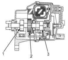
- 1. TDC SENSOR ROTOR
- 2. CKP SENSOR ROTOR
- 3. CYP SENSOR ROTOR
Manifold Absolute Pressure (MAP) Sensor
The MAP sensor converts manifold absolute pressure into electrical signals to the ECM/PCM.
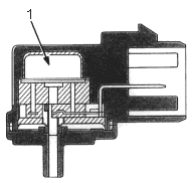
- 1. SENSOR UNIT
PDF p. 1835 · 11-54
Intake Air Temperature (IAT) Sensor
The IAT sensor is a temperature dependant resistor (thermistor). The resistance of the thermistor decreases as the intake air temperature increases.
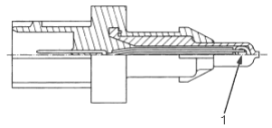
- 1. THERMISTOR
Engine Coolant Temperature (ECT) Sensor
The ECT sensor is a temperature dependant resistor (thermistor). The resistor of the thermistor decreases as the Engine Coolant temperature increases.
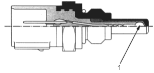
- 1. THERMISTOR
Throttle Position (TP) Sensor
The TP sensor is a potentiometer connected to the throttle valve shaft. As the throttle position changes, the sensor varies the signal voltage to the ECM/PCM. The TP sensor is not replaceable apart from the throttle body.
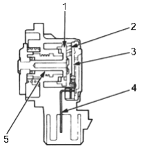
- 1. BRUSH HOLDER
- 2. BRUSH
- 3. RESISTOR
- 4. TERMINAL
- 5. INNER BUSHING
Barometric Pressure (BARO) Sensor
The barometric pressure sensor is inside the ECM/PCM. It converts atmospheric pressure into a voltage signal that modifies the basic duration of the fuel injection discharge.
Primary Heated Oxygen Sensor (PHO2S) and Secondary Heated Oxygen Sensor (SHO2S)
The heated oxygen sensors detect the oxygen content in the exhaust gas, then send signals to the ECM/PCM which varies the duration of fuel injection accordingly. To stabilise its output, the sensors have an internal heater. The primary sensor is installed in the exhaust pipe. The secondary sensor is installed in the TWC.
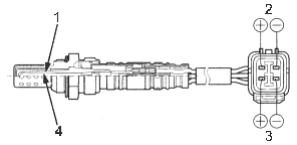
- 1. ZIRCONIA ELEMENT
- 2. SENSOR TERMINALS
- 3. HEATER TERMINALS
- 4. HEATER
By controlling the air/fuel ratio with sensors, the deterioration of the primary sensor can be evaluated by its feedback period. When the feedback period exceeds a certain value during stable driving conditions, the sensor is considered deteriorated and the
ECM/PCM sets a DTC.
Knock Sensor (KS)
The knock control system adjusts the ignition timing for the octane rating of the gasoline used.
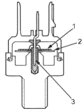
- 1. PIEZO CERAMIC
- 2. DIAPHRAGM
- 3. TERMINAL
PDF p. 1836 · 11-55
Crankshaft Speed Fluctuation (CKF) Sensor
The diagnostic system has a pulser rotor on the crankshaft and a pulse pick-up sensor on the engine block. The ECM/PCM monitors the crankshaft speed fluctuation based on the CKF sensor signal, and judges the air/fuel ratio.
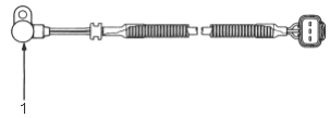
- 1. CKF SENSOR
Exhaust Gas Temperature (EGT) Sensor
The EGT sensor is a temperature dependant resistor (thermistor). The resistance of the thermistor decreases as the exhaust gas temperature increases.
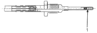
- 1. THERMISTOR