PDF p. 1915 · 11-136
PCM Connector A (32 P)
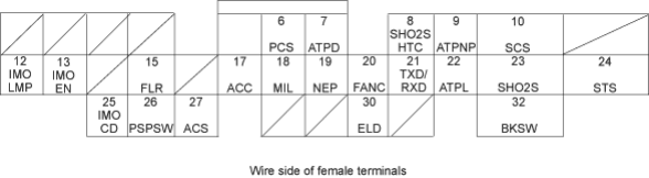
NOTE: Standard battery voltage is 12 V
| Terminal | Wire | Terminal name | Description | Signal |
|---|---|---|---|---|
| number | colour | |||
| 6 | RED | PCS (EVAP PURGE | Drives EVAP purge | With engine running, engine coolant below |
| CONTROL SOLENOID | control solenoid valve. | 74°C (165°F): 0 V | ||
| VALVE) | With engine running, engine coolant | |||
| above 74°C (165°F): battery voltage | ||||
| 7 | GRN | ATPD (AT GEAR | Detects A/T gear | In D position: 0 V |
| POSITION SWITCH) | position switch signal. | In any other position: about 5 V | ||
| 8* | BLK/WHT | SHO2SHTC | Drives secondary | With ignition switch ON (II): battery voltage |
| (SECONDARY | heated oxygen | With fully warmed up engine running: duty | ||
| HEATED OXYGEN | sensor heater. | controlled. | ||
| SENSOR HEATER | ||||
| CONTROL) | ||||
| 9 | LT GRN | ATPNP (AT GEAR | Detects A/T gear | In N or P position: 0 V |
| POSITION SWITCH) | position switch signal. | In any other position: battery voltage | ||
| 10 | BRN | SCS (SERVICE | Detects service | With the terminal connected: 0 V |
| CHECK SIGNAL) | check connector | With the terminal disconnected: about 5 V | ||
| signal (the signal | or battery voltage | |||
| causing a DTC | ||||
| indication) | ||||
| 12 | PNK | IMOLMP | Drives immobiliser | With immobiliser indicator light turned ON: |
| (IMMOBILISER | indicator light. | 0 V | ||
| INDICATOR LIGHT) | With immobiliser indicator light turned | |||
| OFF: battery voltage | ||||
| 13 | BLU | IMOEN | Sends immobiliser | |
| (IMMOBILISER | enable signal. | |||
| ENABLE SIGNAL) | ||||
| 15 | GRN/YEL | FLR (FUEL PUMP | 0 V for two seconds | 0 V for two seconds after turning ignition |
| RELAY) | after turning ignition | switch ON (II), then battery voltage | ||
| switch ON (II), then | ||||
| battery voltage | ||||
| 17 | BLK/RED | ACC (A/C CLUTCH | Drives A/C clutch | With compressor ON: 0 V |
| RELAY) | relay. | With compressor OFF: battery voltage | ||
| 18 | GRN/ORN | MIL (MALFUNCTION | Drives MIL. | With MIL turned ON: 0 V |
| INDICATOR LIGHT) | With MIL turned OFF: battery voltage | |||
| 19 | BLU/BLK | NEP (ENGINE SPEED | Outputs engine | With engine running: pulses |
| PULSE) | speed pulse. | |||
| 20 | GRN | FANC (RADIATOR | Drives radiator fan | With radiator fan running: 0 V |
| FAN CONTROL) | relay. | With radiator fan stopped: battery voltage | ||
| 21 | LT BLU | TXD/RXD (DLC) | Sends and receives | With ignition switch ON (II): about 5 V |
| Honda PGM-Tester | ||||
| signal. | ||||
| 22 | BLU | ATPL (AT GEAR | Detects A/T gear | In L position: 0 V |
| POSITION SWITCH) | position switch signal. | In any other position: battery voltage | ||
| 23* | WHT/RED | SHO2S (SECONDARY | Detects secondary | With throttle fully opened from idle with |
| HEATED OXYGEN | heated oxygen | fully warmed up engine: above 0.6 V | ||
| SENSOR, SENSOR 2) | sensor (sensor 2) | With throttle quickly closed: below 0.4 V | ||
| signal. | ||||
| 24 | BLU/WHT | STS (STARTER | Detects starter switch | With starter switch ON (III): battery voltage |
| SWITCH SIGNAL) | signal. | With starter switch OFF: 0 V | ||
| 25 | RED | IMOCD | Detects immobiliser | |
| (IMMOBILISER CODE) | signal. | |||
| 26 | GRN | PSPSW (P/S | Detects PSP switch | At idle with steering wheel in straight |
| PRESSURE SWITCH | signal. | ahead position: 0 V | ||
| SIGNAL) | At idle with steering wheel at full lock: | |||
| battery voltage | ||||
| 27 | BLU/RED | ACS (A/C SWITCH | Detects A/C switch | With A/C switch ON: 0 V |
| SIGNAL | signal. | With A/C switch OFF: battery voltage | ||
| 30 | GRN/RED | ELD | Detects ELD signal. | With parking lights turned on at idle: about |
| 2.5 - 3.5 V | ||||
| With low beam headlights turned on at | ||||
| idle: about 1.5 - 2.5 V | ||||
| 32 | GRN/WHT | BKSW (BRAKE | Detects brake switch | With brake pedal released: 0 V |
| SWITCH) | signal. | With brake pedal depressed: battery | ||
| voltage | ||||
- *:KQ model
PDF p. 1916 · 11-137
PCM Connector B (25 P)
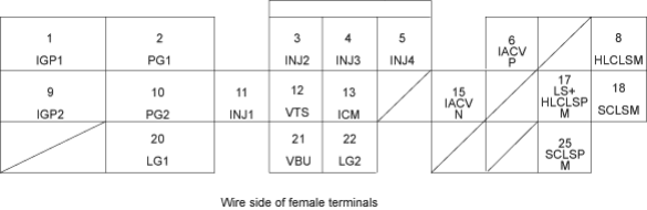
NOTE: Standard battery voltage is 12 V
| Terminal | Wire | Terminal name | Description | Signal |
|---|---|---|---|---|
| number | colour | |||
| 1 | YEL/BLK | IGP1 (POWER | Power source for the | With ignition switch ON (II): battery voltage |
| SOURCE) | PCM control circuit. | With ignition switch OFF: 0 V | ||
| 2 | BLK | PG1 (POWER | Ground for the PCM | Less than 1.0 V at all times |
| GROUND) | control circuit. | |||
| 3 | RED | INJ2 (No. 2 FUEL | Drives No. 2 fuel | With engine running: duty controlled |
| INJECTOR) | injector. | |||
| 4 | BLU | INJ3 (No. 3 FUEL | Drives No. 3 fuel | With engine running: duty controlled |
| INJECTOR) | injector. | |||
| 5 | YEL | INJ4 (No. 4 FUEL | Drives No. 4 fuel | With engine running: duty controlled |
| INJECTOR) | injector. | |||
| 6 | BLK/BLU | IACVP (IDLE AIR | Drives IAC valve | With engine running: duty controlled |
| CONTROL VALVE | (positive side). | |||
| POSITIVE SIDE) | ||||
| 8 | RED/BLK | HLCLSM (PH-PL | PH-PL control linear | With ignition switch ON (II): duty controlled |
| CONTROL LINEAR | solenoid power | |||
| SOLENOID M SIDE) | supply negative | |||
| electrode | ||||
| 9 | YEL/BLK | IGP2 (POWER | Power source for the | With ignition switch ON (II): battery voltage |
| SOURCE) | PCM control circuit. | With ignition switch OFF: 0 V | ||
| 10 | BLK | PG2 (POWER | Ground for the PCM | Less than 1.0 V at all times |
| GROUND) | control circuit. | |||
| 11 | BRN | INJ1 (No. 1 FUEL | Drives No. 1 fuel | With engine running: duty controlled |
| INJECTOR) | injector. | |||
| 12 | GRN/YEL | VTS (VTEC | Drives VTEC | With engine at low rpm: 0 V |
| SOLENOID VALVE) | solenoid valve. | With engine at high rpm (vehicle running): | ||
| battery voltage | ||||
| 13 | YEL/GRN | ICM (IGNITION | Sends ignition pulse. | With ignition switch ON (II): battery voltage |
| CONTROL MODULE) | With engine running: pulses | |||
| 15 | ORN | IACVN (IDLE AIR | Drives IAC valve | With engine running: duty controlled |
| CONTROL VALVE | (negative side). | |||
| NEGATIVE SIDE | ||||
| 17 | GRN/WHT | HLCLSP (PH-PL | PH-PL control linear | With ignition switch ON (II): duty controlled |
| CONTROL LINEAR | solenoid power | |||
| SOLENOID P SIDE) | supply positive | |||
| electrode. | ||||
| 18 | RED/BLU | SCLSM (START | Start clutch control | With ignition switch ON (II): duty controlled |
| CLUTCH CONTROL | linear solenoid power | |||
| LINEAR SOLENOID M | supply negative | |||
| SIDE) | electrode. | |||
| 20 | BRN/BLK | LG1 (LOGIC | Ground for the PCM | Less than 1.0 V at all times |
| GROUND) | control circuit. | |||
| 21 | WHT/BLU | VBU (VOLTAGE BACK | Power source for the | Battery voltage at all times |
| UP) | PCM control circuit. | |||
| Power source for the | ||||
| DTC memory. | ||||
| 22 | BRN/BLK | LG2 (LOGIC | Ground for the PCM | Less than 1.0 V at all times |
| GROUND) | control circuit. | |||
| 25 | YEL | SCLSP (START | Start clutch control | With ignition switch ON (II): duty controlled |
| CLUTCH CONTROL | linear solenoid power | |||
| LINEAR SOLENOID P | supply positive | |||
| SIDE) | electrode. |
PDF p. 1917 · 11-138
PCM Connector C (31 P)
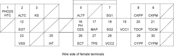
NOTE: Standard battery voltage is 12 V
| Terminal | Wire | Terminal name | Description | Signal |
|---|---|---|---|---|
| number | colour | |||
| 1 | BLK/WHT | PO2SHTC (PRIMARY | Drives primary | With ignition switch ON (II): battery voltage |
| HEATED OXYGEN | heated oxygen | With fully warmed up engine running: duty | ||
| SENSOR HEATER | sensor heater. | controlled | ||
| CONTROL) | ||||
| 2 | WHT/GRN | ALTC (ALTERNATOR | Sends alternator | With fully warmed-up engine running: |
| CONTROL) | control signal. | battery voltage | ||
| During driving with small electrical load: 0 | ||||
| V | ||||
| 3* | RED/BLU | KS (KNOCK SENSOR) | Detects KS signal. | With engine knocking: pulses |
| 5 | WHT/RED | ALTF (ALTERNATOR | Detects alternator FR | With fully warmed-up engine running: 0 V - |
| FR SIGNAL) | signal. | battery voltage (depending on electrical | ||
| load) | ||||
| 7 | GRN/WHT | SG1 (SENSOR | Ground for MAP | Less than 1.0 V at all times |
| GROUND) | sensor. | |||
| 8 | BLU | CKPP (CKP SENSOR | Detects CKP sensor. | With engine running: pulses |
| P SIDE) | ||||
| 9 | WHT | CKPM (CKP SENSOR | Ground for CKP | |
| M SIDE) | sensor. | |||
| 12* | BLK/WHT | EGT (EXHAUST GAS | Detects EGT sensor | With ignition switch ON (II): about 0.1 - 4.8 |
| TEMPERATURE | signal. | V (depending on exhaust gas temperature) | ||
| SENSOR) | ||||
| 16 | WHT | PHO2S (PRIMARY | Detects primary | With throttle fully opened from idle with |
| HEATED OXYGEN | heated oxygen | fully warmed up engine: above 0.6 V | ||
| SENSOR, SENSOR 1) | sensor (sensor 1) | With throttle quickly closed: below 0.4 V | ||
| signal. | ||||
| 17 | RED/GRN | MAP (MANIFOLD | Detects MAP sensor | With ignition switch ON (II): about 3 V |
| ABSOLUTE | signal. | At idle: about 1.0 V (depending on engine | ||
| PRESSURE SENSOR) | speed) | |||
| 18 | GRN/BLK | SG2 (SENSOR | Sensor ground. | Less than 1.0 V at all times |
| GROUND) | ||||
| 19 | YEL/RED | VCC1 (SENSOR | Power source to MAP | With ignition switch ON (II): about 5 V |
| VOLTAGE) | sensor. | With ignition switch OFF: 0 V | ||
| 20 | GRN | TDCP (TDC SENSOR | Detects TDC sensor. | With engine running: pulses |
| P SIDE) | ||||
| 21 | RED | TDCM (TDC SENSOR | Ground for TDC | |
| M SIDE) | sensor. | |||
| 23 | BLU/WHT | VSS (VEHICLE | Detects VSS signal. | With ignition switch ON (II) and front wheel |
| SPEED SENSOR) | rotating: cycles 0 V - 5 V | |||
| 25 | RED/YEL | IAT (INTAKE AIR | Detects IAT sensor | With ignition switch ON (II): about 0.1 - 4.8 |
| TEMPERATURE | signal. | V (depending on intake air temperature) | ||
| SENSOR) | ||||
| 26 | RED/WHT | ECT (ENGINE | Detects ECT sensor | With ignition switch ON (II): about 0.1 - 4.8 |
| COOLANT | signal. | V (depending on engine coolant | ||
| TEMPERATURE | temperature) | |||
| SENSOR) | ||||
| 27 | RED/BLK | TPS (THROTTLE | Detects TP sensor | With throttle fully open: 4.8 V |
| POSITION SENSOR) | signal. | With throttle fully closed: about 0.5 V | ||
| 28 | YEL/BLU | VCC2 (SENSOR | Provides sensor | With ignition switch ON (II): about 5 V |
| VOLTAGE) | voltage. | With ignition switch OFF: 0 V | ||
| 29 | YEL | CYPP (CYP SENSOR | Detects CYP sensor. | With engine running: pulses |
| P SIDE) | ||||
| 30 | BLK | CYPM (CYP SENSOR | Ground for CYP | |
| M SIDE) | sensor. | |||
- *:KQ model
PDF p. 1918 · 11-139
PCM Connector D (16 P)
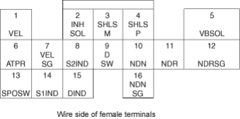
NOTE: Standard battery voltage is 12 V
| Terminal | Wire | Terminal name | Description | Signal | ||
|---|---|---|---|---|---|---|
| number | colour | |||||
| 1 | WHT/RED | VEL (SECONDARY | Secondary gear shaft | Depending on vehicle speed: pulses | ||
| GEAR SHAFT SPEED | speed sensor. | When vehicle is stopped: 0 V | ||||
| SENSOR) | ||||||
| 2 | GRN | INHSOL (INHIBITOR | Inhibitor solenoid | With inhibitor solenoid ON: battery voltage | ||
| SOLENOID | control. | With inhibitor solenoid OFF: 0 V | ||||
| CONTROL) | ||||||
| 3 | GRN/YEL | SHLS M (SHIFT | Shift control linear | With ignition switch ON (II): pulses | ||
| CONTROL LINEAR | solenoid power | |||||
| SOLENOID M SIDE) | supply negative | |||||
| electrode. | ||||||
| 4 | BLU/WHT | SHLS P (SHIFT | Shift control linear | With ignition switch ON (II): pulses | ||
| CONTROL LINEAR | solenoid power | |||||
| SOLENOID P SIDE) | supply positive | |||||
| electrode. | ||||||
| 5 | BLK/YEL | VBSOL (BATTERY | Power source of | With ignition switch ON (II): battery voltage | ||
| VOLTAGE FOR | solenoid valve. | With ignition switch OFF: 0 V | ||||
| SOLENOID VALVE) | ||||||
| 6 | WHT | ATPR (AT GEAR | Detects A/T gear | In R position: 0 V | ||
| POSITION SWITCH) | position switch signal. | In any other position: battery voltage | ||||
| 7 | BLK/WHT | VELSG (SECONDARY | Ground for secondary | |||
| GEAR SHAFT SPEED | gear shaft speed | |||||
| SENSOR GROUND) | sensor. | |||||
| 8 | LT GRN | S2IND (S2 | Drives  indicator. | With  indicator turned ON: battery | ||
| INDICATOR LIGHT) | voltage | |||||
With  indicator turned OFF: 0 V | ||||||
| 9 | BLU | DSW (D MODE | Detects D mode | With D mode switch ON: 0 V | ||
| SWITCH) | switch signal. | With D mode switch OFF: battery voltage | ||||
| 10 | WHT | NDN (DRIVEN | Detects driven pulley | In other than N or P positions: pulses | ||
| PULLEY SPEED | speed sensor signal. | |||||
| SENSOR) | ||||||
| 11 | RED/BLU | NDR (DRIVE PULLEY | Detects drive pulley | In other than N or P position: pulses | ||
| SPEED SENSOR) | speed sensor signal. | |||||
| 12 | GRN | NDRSG (DRIVE | Ground for drive | |||
| PULLEY SPEED | pulley speed sensor. | |||||
| SENSOR GROUND) | ||||||
| 13 | YEL | SPOSW (S MODE | Detects | mode switch | With | mode switch ON: 0 V |
| SWITCH) | signal. | With | mode switch OFF: battery voltage | |||
| 14 | GRN/RED | S1IND (S1 | Drives  indicator. | With  indicator turned ON: battery | ||
| INDICATOR LIGHT) | voltage | |||||
With  indicator turned OFF: 0 V | ||||||
| 15 | GRN/BLK | DIND (D INDICATOR | Drives D indicator. | With D indicator turned ON: battery | ||
| LIGHT) | voltage | |||||
| With D indicator turned OFF: 0 V | ||||||
| 16 | RED/WHT | NDNSG (DRIVEN | Ground for driven | |||
| PULLEY SPEED | pulley speed sensor. | |||||
| SENSOR GROUND) | ||||||