PDF p. 1894 · 11-113
Positive Crankcase Ventilation (PCV) System
The Positive Crankcase Ventilation (PCV) system is designed to prevent blow-by gas from escaping to the atmosphere. The PCV valve contains a spring-loaded plunger. When the engine starts, the plunger in the PCV valve is lifted in proportion to the intake manifold vacuum and the blow-by gas is drawn directly into the intake manifold.
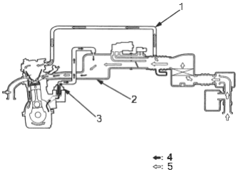
- 1. BREATHER PIPE
- 2. INTAKE MANIFOLD
- 3. PCV VALVE
- 4. BLOW-BY VAPOUR
- 5. FRESH AIR
PDF p. 1895 · 11-114
Evaporative Emission (EVAP) Control System Diagram
The evaporative emission control minimises the amount of fuel vapour escaping to the atmosphere. Vapour from the fuel tank is temporarily stored in the EVAP control canister until it can be purged from the canister into the engine and burned.
- The EVAP control canister is purged by drawing fresh air through it and into a port on the intake manifold. The purging vacuum is controlled by the EVAP purge control solenoid valve, which is open whenever engine coolant temperature is above 68°C (154°F).
- When vapour pressure in the fuel tank is higher then the set value of the EVAP two way valve, the valve opens and regulates the flow of fuel vapour to the EVAP control canister. D16W1 engine:
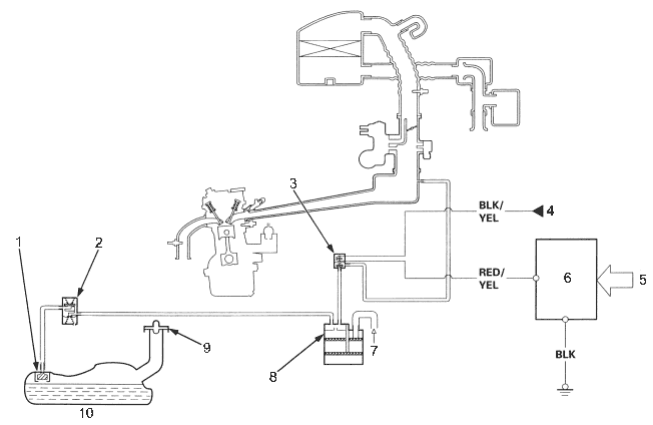
- 1. FUEL TANK EVAP VALVE
- 2. EVAP TWO WAY VALVE
- 3. EVAP PURGE CONTROL SOLENOID VALVE
- 4. INSTRUMENT LIGHT (7.5 A) FUSE
- 5. VARIOUS SENSORS
- 6. ECM/PCM
- 7. FRESH AIR
- 8. EVAP CONTROL CANISTER
- 9. FUEL FILL CAP
- 10. FUEL TANK
PDF p. 1896 · 11-115
D16W5 engine:
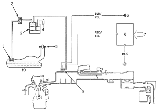
- 1. FUEL TANK EVAP VALVE
- 2. EVAP CONTROL CANISTER
- 3. EVAP TWO WAY VALVE
- 4. FRESH AIR
- 5. FUEL FILL CAP
- 6. INSTRUMENT LIGHT (7.5 A) FUSE
- 7. VARIOUS SENSORS
- 8. ECM/PCM
- 9. EVAP PURGE CONTROL SOLENOID VALVE