PDF p. 404 · 11-74
System Troubleshooting Guide
NOTE: Across each row in the chart, the sub-systems that could be sources of a symptom are ranked in the order they should be inspected starting with 1. Find the symptom in the left column, read across to the most likely source, then refer to the page listed at the top of that column, If inspection shows the system is OK, try the next most likely system 2. etc.
| SUB-SYSTEM | FUEL LINES | FUEL | FUEL | FUEL | FUEL | PGM/FI MAIN | CONTAMINATED | |
|---|---|---|---|---|---|---|---|---|
| INJECTOR | PRESSURE | FILTER | PUMP | RELAY | FUEL | |||
| REGULATOR | ||||||||
| PAGE | 11-75 | 11-81 | 11-85 | 11-86 | 11-87 | 11-92 | - | |
| SYMPTOM | ||||||||
| ENGINE WILL NOT START | 3 | 3 | 1 | 2 | ||||
| DIFFICULT TO START ENGINE WHEN COLD OR | 1 | 2 | ||||||
| HOT | ||||||||
| ROUGH IDLE | 1 | 2 | ||||||
| POOR | MISFIRE OR ROUGH | 1 | 2 | 2 | ||||
| PERFORMANCE | RUNNING | |||||||
| POOR | FAILS EMISSION TEST | 2 | 1 | |||||
| PERFORMANCE | ||||||||
| POOR | LOSS OF POWER | 3 | 2 | 1 | ||||
| PERFORMANCE | ||||||||
| FREQUENT | WHILE WARMING UP | 1 | ||||||
| STALLING | ||||||||
| FREQUENT | AFTER WARMING UP | 1 | ||||||
| STALLING | ||||||||
PDF p. 405 · 11-75
Fuel Lines
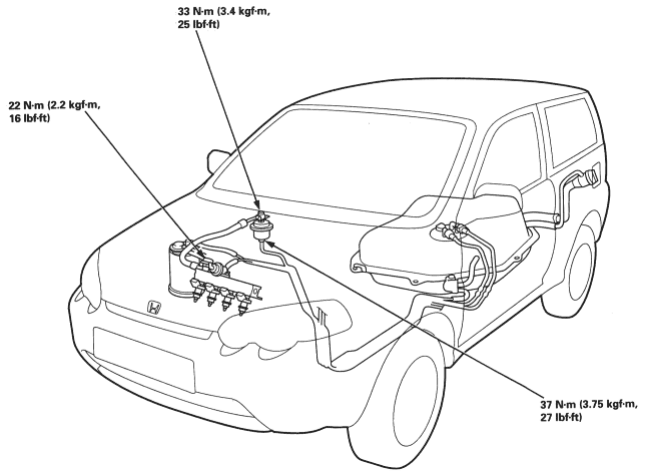
NOTE: Check fuel system lines, hoses and fuel filter for damage, leaks or deterioration and replace if necessary
PDF p. 406 · 11-76
NOTE: Check all hose clamps and retighten if necessary.
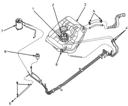
- 1. BASE PACKING, Replace
- 2. FUEL PUMP/FUEL GAUGE SENDING UNIT
- 3. FUEL TANK
- 4. FUEL TUBE/QUICK-CONNECT FITTINGS
- 5. To FUEL PRESSURE REGULATOR
- 6. FUEL FILTER
- 7. EVAPORATIVE EMISSION (EVAP) CONTROL CANISTER
- 8. EVAPORATIVE EMISSION (EVAP) TWO WAY VALVE
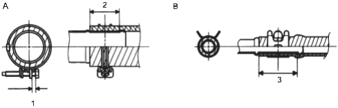
- 1. 10-14 mm (0.39-0.55 in)
- 2. Clamp in the middle
- 3. Clamp in the middle
PDF p. 407 · 11-77
Fuel Tube/Quick-Connect Fittings
Precautions
The fuel tube/quick-connect fittings assembly connects the in-tank fuel pump with the fuel filter and the fuel return pipe, the fuel filter with the fuel feed pipe. For removing or installing the fuel filter, the fuel pump and fuel tank, it is necessary to disconnect or connect the quick-connect fittings.
Pay attention to the following:
- The fuel tube/quick-connect fittings assembly is not hear-resistant, be careful not to damage it during welding or other heat-generating procedures.
- The fuel tube/quick-connect fittings assembly is not acid-proof, do not touch it with a shop towel which was used for wiping battery electrolyte. Replace the fuel tube/quick-connect fittings assembly if it came into contact with electrolyte or something similar.
- When connecting or disconnecting the fuel tube/quick-connect fittings assembly, be careful not to bend or twist it excessively. Replace it if damaged.
A disconnected quick-connect fittings can be reconnected, but the retainer on the mating pipe cannot be reused one it has been removed from the pipe. Replace the retainer when:
- replacing the fuel pump.
- replacing the fuel feed pip.
- it has been removed from the pipe.
- it is damaged.
- 1. CONNECTOR
- 2. FUEL TUBE
- 3. RETAINER
Disconnections
- 1.Disconnect the battery negative cable.
- 2.Remove the fuel fill cap and relieve fuel pressure in the tank.
- 3.Relieve fuel pressure (See Page 11-80).
- 4.Check the fuel quick-connect fittings for dirt and clean if necessary.
- 5.
Hold the connector with one hand and press down the retainer tabs with the other hand, then pull the connector off.
NOTE:
- Be careful not to damage the pipe or other parts. Do not use tools
- If the connector does not move, keep the retainer tabs pressed down and alternately pull and push the connector until it comes off easily.
- Do not remove the retainer from the pipe; once removed, the retainer must be replaced with a new one.
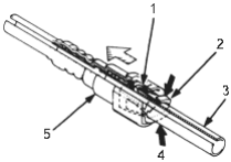
- 1. LOCKING PAWL
- 2. RETAINER TAB
- 3. PIPE
- 4. Press down
- 5. CONNECTOR
- 6.Check the contact area of the pipe for dirt and damage.
- If the surface is dirty, clean it.
- If the surface is rusty or damaged, replace the fuel pump or fuel feed pipe.
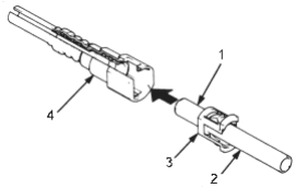
- 1. CONTACT AREA
- 2. PIPE
- 3. RETAINER
- 4. CONNECTOR
PDF p. 408 · 11-78
- 7.To prevent damage and keep out foreign matter cover the disconnected connector and pipe end with plastic bags.
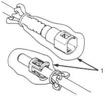
- 1. PLASTIC BAGS
NOTE:
The retainer cannot be reused once it has been removed from the pipe.
Replace the retainer when
- replacing the fuel pump.
- replacing the fuel feed pipe.
- it has been removed from the pipe.
- it is damaged.
Connection
- 1.Check the pipe contact area for dirt and damage and clean it necessary.
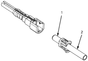
- 1. CONTACT AREA
- 2. PIPE
- 2.Insert a new retainer into the connector if the retainer is damaged, or after:
- replacing the fuel pump.
- replacing the fuel feed pipe.
- removing the retainer from the pipe.
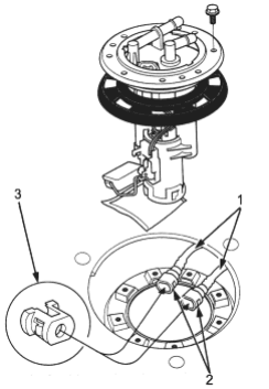
- 1. FUEL TUBES
- 2. CONNECTORS
- 3. New RETAINER (Insert into the connector.)
PDF p. 409 · 11-79
Before connecting a new fuel tube/quick-connect fitting assembly, remove the old retainer from the mating pipe.
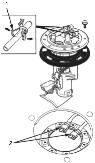
- 1. RETAINER
With the tabs pulled apart, pull the retainer off - 2. New FUEL TUBE/QUICK-CONNECT FITTING ASSEMBLY
- 3.
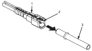
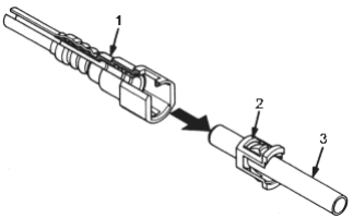
Align the quick-connect fittings with the pipe and align the retainer locking pawls with the connector grooves. Then press the quick-connect fittings onto the pipe until both retainer pawls lock with a clicking sound.
NOTE: If it is hard to connect, put a small amount of new engine oil on the pipe end.
Connection with new retainer:
Reconnection to existing retainer:
- 1. CONNECTOR
- 2. RETAINER
- 3. PIPE
- 1. CONNECTOR
- 2. RETAINER
- 3. PIPE
- 4.Make sure the connection is secure and that the pawls are firmly locked into place; check visually and by pulling the connector.
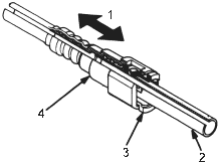
- 1. Pull apart.
- 2. PIPE
- 3. RETAINER
- 4. CONNECTOR
- 5.Reconnect the battery negative cable and turn the ignition switch ON (II). The fuel pump will run for about two seconds and fuel pressure will rise. Repeat two or three times and check that there is no leakage in the fuel supply system.
- 1.CONNECTOR
- 2.RETAINER
- 3.PIPE
PDF p. 410 · 11-80
System Description
The fuel supply system consists of a fuel tank, in-tank high-pressure fuel pump, PGM-FI main relay, fuel filter, fuel pressure regulator, fuel injectors and fuel delivery and return lines. This system delivers pressure-regulated fuel to the fuel injectors and cuts the fuel delivery when the engine is not running.
Fuel Pressure
Relieving
Before disconnecting fuel pipes or hoses, release pressure from the system by loosening the 12 mm banjo bolt on top of the fuel filter.
- 1.Write down the frequencies for the radio’s preset buttons.
- 2.Disconnect the battery negative cable from the battery negative terminal.
- 3.Remove the fuel fill cap.
- 4.Use a box end wrench on the 12 mm banjo bolt at the fuel filter, while holding the fuel filter with another wrench.
- 5.Place a rag or shop towel over the 12 mm banjo bolt.
- 6.Slowly loosen the 12 mm banjo bolt one complete turn.
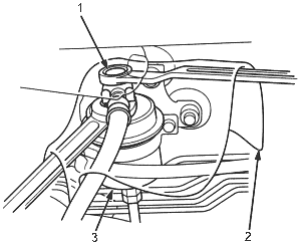
- 1. 12 mm BANJO BOLT, 33 Nm (3.4 kgf/m, 25 lbf/ft)
- 2. SHOP TOWEL
- 3. FUEL FILTER
NOTE: Replace the washers whenever the 12 mm banjo bolt is loosed or removed.
- 7.Reconnect the battery, then enter the customer’s radio station presets.
PDF p. 411 · 11-81
Inspection
- 1.Relieve fuel pressure (see page 11-80).
- 2.Remove the 12 mm banjo bolt on the fuel filter while holding the fuel filter with another wrench. Attach the 12 mm fuel pressure adapter bolt and the special tool.
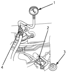
- 1. FUEL PRESSURE GAUGE SET 07406-0040002
- 2. CLAMP
- 3. FUEL PRESSURE REGULATOR
- 4. FUEL PRESSURE ADAPTER BOLT, 12 mm (90008-PD6-010)
- 3.
Start the engine. Measure the fuel pressure with the engine idling and the vacuum hose of the fuel pressure regulator disconnected from the fuel pressure regulator and pinched. If the engine will not start, turn the ignition switch ON (II). wait for two seconds, turn it off, then back on again and read the fuel pressure.
Pressure should be:
260-310 kPa (2.7-3.2 kgf/cm2, 38-46 psi)
- 4.
Reconnect vacuum hose to the fuel pressure regulator.
Pressure should be:
200-250 kPa (2.0-2.5 kgf/cm2, 28-36 psi)
If the fuel pressure is not as specified, first check the fuel pump (See Page 11-87). If the fuel pump is OK, check the following:
- If the fuel pressure is higher than specified, inspect for:
- Pinched or clogged fuel return hose or line.
- Faulty fuel pressure regulator (See Page 11-85).
- If the fuel pressure is lower than specified, inspect for:
- Clogged fuel filter.
- Faulty fuel pressure regulator (See Page 11-85).
- Leakage in the fuel line.
- If the fuel pressure is higher than specified, inspect for:
Fuel Injectors
Description
The fuel injectors are a solenoid-actuated constant-stroke, pintle-type consisting of a solenoid, plunger needle valve and housing. When current is applied to the solenoid coil, the valve lifts up and pressurised fuel is injected. Because the needle valve lift and the fuel pressure are constant, the injection quantity is determined by the length of time and the valve is open (that is the duration the current is supplied to the solenoid coil). The fuel injector is sealed by an O-ring and seal ring at the top and bottom. These seals also reduce operating noise.
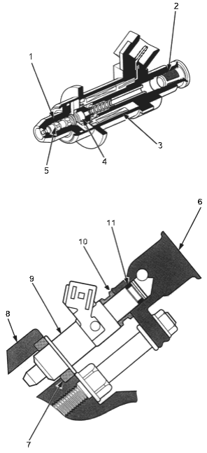
- 1. PLUNGER HOUSING
- 2. FILTER
- 3. SOLENOID COIL
- 4. CORE
- 5. PLUNGER
- 6. FUEL RAIL
- 7. SEAL RING
- 8. INTAKE MANIFOLD
- 9. FUEL INJECTOR
- 10. CUSHION RING
11 O-RING
PDF p. 412 · 11-82
Testing
NOTE: Check the following times before testing: idle speed, ignition timing and idle CO%.
If the engine runs:
- 1.With the engine idling, disconnect each fuel injector connector individually and inspect the change in the idle speed.
- If the idle speed drop is almost the same for each cylinder, the fuel injectors are normal.
- If the idle speed or quality remains the same when you disconnect a particular fuel injector, replace the fuel injector and retest.
- 2.Check the clicking sound of each fuel injector by means of a stethoscope when the engine is idling.
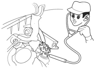
- If any fuel injector fails to make the typical clicking sound, check the sound again after replacing the fuel injector.
- If clicking sound is still absent, check the following:
- Whether there is any short-circuiting, wire breakage or poor connection in the YEL/BLK wire between the PGM-FI main relay and the junction connector.
- Whether the junction connector is open or corroded.
- Whether there is any short-circuiting, wire breakage or poor connection in the YEL/BLK wire between the junction connector and the fuel injector.
- Whether there is any short-circuiting, wire breakage or poor connection in the wire between the fuel injector and the ECM/PCM. If all is OK, check the ECM/PCM (See Page 11-27) and PGM-FI main relay (see page 11-92).
Testing
- 1.
Remove the connector of the fuel injector and measure the resistance between the 2 terminals of the fuel injector.
Resistance should be: 12-15 ohm
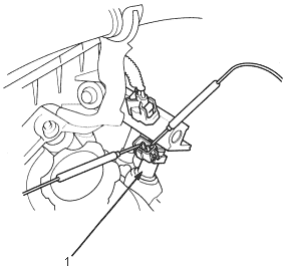
- 1. FUEL INJECTOR
- If the resistance is not as specified, replace the fuel injector.
- If the resistance is as specified, check the fuel pressure (see page 11-81).
- If the fuel pressure is as specified, check the following:
- Whether there is any short-circuiting, wire breakage or poor connection in the YEL/BLK wire between the PGM-FI main relay and the junction connector.
- Whether the junction connector is open or corroded.
- Whether there is any short-circuiting, wire breakage or poor connection in the YEL/BLK wire between the junction connector and the fuel injector.
- Whether there is any short-circuiting, wire breakage or poor connection in the wire between the fuel injector and the ECM/PCM.
If all is OK check the ECM/PCM (See Page 11-27).
PDF p. 413 · 11-83
Replacement
- 1.Relieve the fuel pressure (See Page 11-80).
- 2.Remove the air cleaner housing.
- 3.Disconnect the connectors from the fuel injectors.
- 4.
Disconnect the vacuum hoses and fuel return hose from the fuel pressure regulator.
NOTE: Place a rag or shop towel over the hoses before disconnecting them.
- 5.Disconnect the fuel feed hose from the fuel rail.
- 6.Remove the retainer nuts from the fuel rail.
- 7.Disconnect the fuel rail.
- 8.Remove the fuel injectors from the intake manifold.
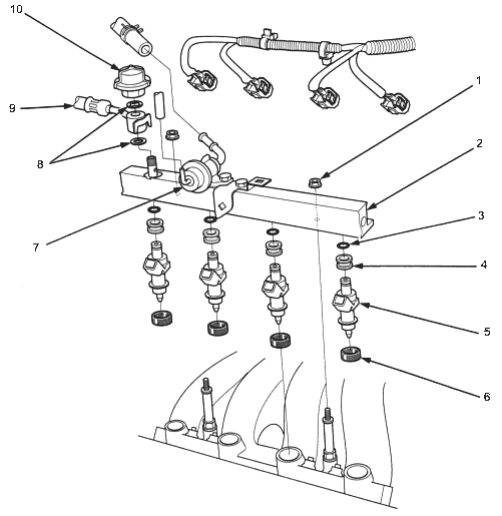
- 9.Slide new cushion rings onto the fuel injectors.
- 10.Coat new O-rings with clean engine oil and put them on the fuel injectors.
- 11.Insert the fuel injectors into the fuel rail first.
- 12.Coat new seal rings with clean engine oil and press them into the intake manifold.
- 1.12 Nm (1.2 kgf/m, 8.7 lbf/ft)
- 2.FUEL RAIL
- 3.O-RING, Replace
- 4.CUSHION RING, Replace
- 5.FUEL INJECTOR
- 6.SEAL RING, Replace
- 7.FUEL PRESSURE REGULATOR
- 8.WASHER, Replace
- 9.FUEL FEED HOSE
- 10.
FUEL PULSATION DAMPER
22 Nm (2.2 kgf/m, 16 lbf/ft)
PDF p. 414 · 11-84
.
13.. To prevent damage to the O-rings, install the fuel injectors in the fuel rail first, then install them in the intake manifold.
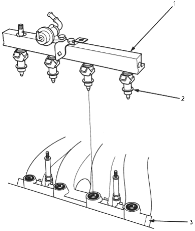
- 14.Install and tighten the retainer nuts.
- 15.Connect the fuel hose to the fuel rail with new washers.
- 16.Connect the vacuum hoses and fuel return hose to the fuel pressure regulator.
- 17.Install the connectors on the fuel injectors.
- 18.Install the air cleaner housing.
- 1.FUEL RAIL
- 2.FUEL INJECTOR
- 3.INTAKE MANIFOLD
- 19.Turn the ignition switch ON (II), but do not operate the starter. After the fuel pump runs for approximately two seconds, the fuel pressure in the fuel line rises. Repeat this two or three times, then check whether there is any fuel leakage.
PDF p. 415 · 11-85
Fuel Pressure Regulator
Description
The fuel pressure regulator maintains a constant fuel pressure to the fuel injectors. When the difference between the fuel pressure and manifold pressure exceeds 290 kPa (3.0 kgf/m, 43 psi), the diaphragm is pushed upward, and the excess fuel is fed back into the fuel tank through the return line.
CLOSED:
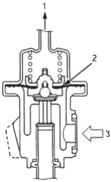
- 1. To INTAKE MANIFOLD
- 2. DIAPHRAGM
- 3. FUEL INLET
OPEN:
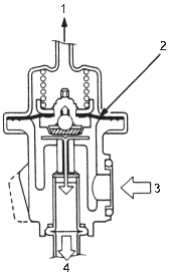
- 1. To INTAKE MANIFOLD
- 2. DIAPHRAGM
- 3. FUEL INLET
- 4. FUEL RETURN
Testing
- 1.Attach the special tool and the 12 mm fuel pressure adapter bolt to the fuel filter (See Page 11-81).
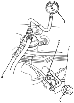
- 1. FUEL PRESSURE GAUGE SET, 07406-0040002
- 2. CLAMP
- 3. FUEL PRESSURE REGULATOR
- 4. FUEL PRESSURE ADAPTER BOLT, 12 mm (90008-PD6-010)
Pressure should be:
260-310 kPa (2.7-3.2 kgf/cm2, 38-46 psi)
(with the fuel pressure regulator vacuum hose disconnected and pinched)
- 2.Reconnect the vacuum hose to the fuel pressure regulator.
- 3.Check that the fuel pressure rises when the vacuum hose from the fuel pressure regulator is disconnected again.
- If the fuel pressure did not rise, replace the fuel pressure regulator.
PDF p. 416 · 11-86
Replacement
- 1.Place a shop towel under the fuel pressure regulator, then relieve fuel pressure (See Page 11-80).
- 2.Disconnect the vacuum hose and fuel return hose.
- 3.Remove the two 6 mm retainer bolts and the fuel pressure regulator
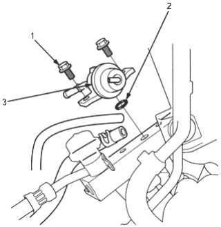
- 1. 12 Nm (1.2 kgf/m, 8.7 lbf/ft)
- 2. O-RING Replace.
- 3. FUEL PRESSURE REGULATOR
- 4.Apply clean engine oil to a new O-ring and carefully install it into its proper position.
- 5.Install the fuel pressure regulator in the reverse order of removal.
Fuel Filter
Replacement
The fuel filter should be replaced whenever the fuel pressure drops below the specified value (260-310 kPa (2.7-3.2 kgf/cm2, 38-46 psi) with the fuel pressure regulator vacuum hose disconnected and pinched), after making sure that the fuel pump and the fuel pressure regulator are OK.
- 1.Disconnect the battery negative cable from the battery negative terminal.
- 2.Place a shop towel under and around the fuel filter.
- 3.Relieve fuel pressure (See Page 11-80).
- 4.Remove the 12 mm sealing bolt and the fuel feed pipe from the fuel filter, while supporting it with another wrench, as shown.
- 5.Remove the fuel filter clamp and fuel filter.
- 6.Install the new fuel filter in the reverse order of removal and note these items:
- When assembling, use new washers as shown.
- Clean the flared joint of high pressure hoses thoroughly before reconnecting them.
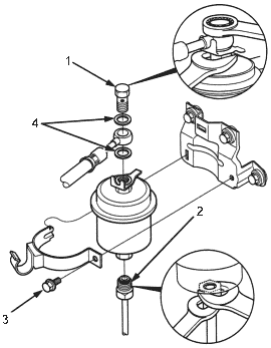
- 1. 12 mm SEALING BOLT 33 Nm (3.4 kgf/m, 25 lbf/ft)
- 2. 37 Nm (3.8 kgf/m, 27 lbf/ft)
- 3. 9.8 Nm (1.0 kgf/m, 7.2 lbf/ft)
- 4. WASHER Replace
PDF p. 417 · 11-87
Fuel Pump
Testing
If you suspect a problem with the fuel pump, check that the fuel pump actually runs; when it is ON (II), you will hear some noise if you hold your ear to the fuel fill port with the fuel fill cap removed. The fuel pump should run for two seconds when ignition switch is first turned ON (II). If the fuel pump does not make a noise, check it as follows.
- 1.Remove the access panel from the floor.
- 2.Turn the ignition switch OFF, then disconnect the 5P connector from fuel pump.
- 3.
Connect the PGM-FI main relay 7P connector terminal No. 4 and No. 5 with a jumper wire.
PGM-FI MAIN RELAY 7P CONNECTOR
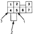
Wire side of female terminals
- 1.IG1 (BLK/RED)
- 2.JUMPER WIRE
- 3.FUEL PUMP (YEL/GRN)
- 4.
Check that battery voltage is available between the fuel pump 5P connector terminal No. 5 and body ground when the ignition switch is turned ON (II).
FUEL PUMP 5P CONNECTOR
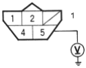
Wire side of female terminals
- 1.FUEL PUMP (YEL/GRN)
- If battery voltage is available, check the fuel pump ground. If the ground is OK, replace the fuel pump.
- If there is no voltage, check the wire harness (see page 11-93).
Replacement
- 1.Relieve fuel pressure (See Page 11-80).
- 2.Remove the access panel from the floor.
- 3.Turn the ignition switch OFF, then disconnect the fuel pump 5P connector.
- 4.Disconnect the quick-connect fittings from the fuel pump.
- 5.Remove the bolts and the fuel pump assembly.
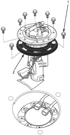
- 1. 4 Nm (0.4 kgf/m, 3 lbf/ft)
- 2. BASE GASKET Replace
PDF p. 418 · 11-88
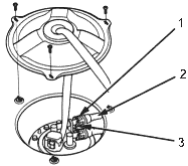
- 5.Remove the bracket, the fuel gauge sending unit, the hose and the wire harness.
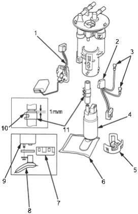
- 1. FUEL SENDING UNIT
- 2. WIRE HARNESS
- 3. TERMINAL
- 4. FUEL PUMP
- 5. BRACKET
- 6. SUCTION FILTER
- 7. BRACKET
- 8. SUCTION FILTER
- 9. FUEL PUMP
- 10. TAB
- 11. CLAMP
- 6.When connecting the fuel pump, make sure the connection is secure and the suction filter is firmly connected to the fuel pump.
- 7.Install the part in the reverse order of removal with a new base gasket, then checking these items:
- When connecting the wire harness, make sure the connection is secure and the terminal is firmly locked into the place.
- Check that the tab of the clamp do not interfere with the wire harness.
- Do not push the lower part of suction filter.
- When installing the fuel gauge sending unit, make sure the connection is secure and the connector is firmly locked into the place. Be careful not to bend or twist it excessively.
Fuel Gauge
Testing
NOTE: See section 23 for the fuel gauge system circuit diagram.
- 1.Check the INSTRUMENT LIGHT (7.5A) fuse in the under-dash fuse/relay box before testing.
- 2.Remove the access panel from the floor.
- 3.Turn the ignition switch OFF, then disconnect the fuel pump 5P connector.
- 4.
Measure voltage between the fuel pump 5P connector terminals No. 1 and No. 2 with the ignition switch ON (II).
There should be between 5 and 8 V.
FUEL PUMP 5P CONNECTOR
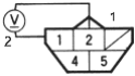
Wire side of female terminals
- 1.(YEL/BLK)
- 2.(BLK)
- If the voltage is as specified, go to step 6.
- If the voltage is not as specified, check for:
- an open in the YEL/BLK or BLK wire.
- poor ground (G501).
- 5.Turn the ignition switch OFF.
- 6.
Connect the fuel pump 5P connector terminals No. 1 and No. 2 with a jumper wire, then turn the ignition switch ON (II).
FUEL PUMP 5P CONNECTOR
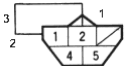
Wire side of female terminals
- 1.(YEL/BLK)
- 2.(BLK)
- 3.JUMPER WIRE
PDF p. 419 · 11-89
- 8.Check that the pointer of the fuel gauge starts moving toward the “F” mark.
- If the pointer of the fuel gauge does not move at all, replace the gauge.
- If the gauge is OK, inspect the fuel gauge sending unit.
NOTE:
- Turn the ignition switch OFF before the pointer reaches “F” on the gauge dial. Failure to do so may damage the fuel gauge.
- The fuel gauge is a bobbin (cross-coil) type, hence the fuel level is continuously indicated even when the ignition switch is OFF, and the pointer moves more slowly than that of a bimetal type.
Fuel Gauge Sending Unit
Testing
- 1.Relieve fuel pressure (See Page 11-80).
- 2.Remove the access panel from the floor.
- 3.Turn the ignition switch OFF, then disconnect the fuel pump 5P connector.
- 4.Disconnect the quick-connect fittings from the fuel pump.
- 5.Remove the bolts and the fuel pump assembly.
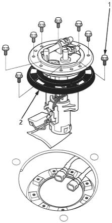
- 1. 4 Nm (0.4 kgf/m, 3 lbf/ft)
- 2. BASE GASKET, Replace
PDF p. 420 · 11-90
- 6.Measure the resistance between the No. 1 and No.2 terminals at E (EMPTY), 1/2 (HALF FULL) and F (FULL) by moving the float.
| Float Position | E | 1/2 | F | |
| Resistance (ohms) 130-132 68.5-74.5 | 11-13 | |||
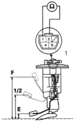
Top of the workbench (Bottom of the fuel tank)
- 1.Terminal side of male terminals
If you do not get the above readings, replace the fuel gauge sending unit.
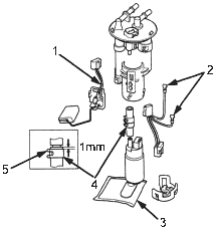
- 1. FUEL GAUGE SENDING UNIT
- 2. TERMINAL
- 3. SUCTION FILTER
- 4. CLAMP
- 5. TAB
- 7.Install the part in the reverse order of removal with a new base gasket, then checking these items:
- When connecting the wire harness, make sure the connection is secure and the terminal is firmly locked into the place.
- Check that the tab of the clamp do not interfere with the wire harness.
- Do not push the lower part of suction filter.
- When installing the fuel gauge sending unit, make sure the connection is secure and the connector is firmly locked into the place. Be careful not to bend or twist it excessively.
Low Fuel Indicator Light System
Indicator Light Testing
NOTE: See section 23 for the low fuel indicator circuit diagram:
- 1.Check the INSTRUMENT LIGHT (7.5A) fuse in the under-dash fuse/relay before testing.
- 2.Park the vehicle on level ground.
- 3.Drain the fuel tank: Remove the fuel return line from the fuel pressure regulator and attach a suitable hose to the regulator fitting. Place the other end of the hose in a container suitable for gasoline. Start the engine and run it until the tank is empty (the engine stalls).
- 4.Add less than 6.9 l (1.8 U.S. Gal, 1.5 Imp, Gal) of fuel and turn the ignition switch ON (II). The low fuel indicator light should come on within four minutes.
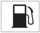
LOW FUEL INDICATOR LIGHT
- If the light comes on within four minutes, go to step 9.
- If the light does not come on within four minutes, go to step 5.
- 5.Remove the access panel from the door.
- 6.Turn the ignition switch OFF, then disconnect the fuel pump 5P connector.
PDF p. 421 · 11-91
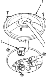
- 1. ACCESS PANEL
- 2. 5P CONNECTOR
- 7.Turn the ignition switch ON (II).
- If the light comes on, replace the fuel gauge sending unit (see page 11-90).
- If the light does not come on, check for:
- an open in the YEL/BLK wire between the fuel gauge sending unit and fuel gauge assembly.
- blown bulb.
- poor ground (G501).
- Faulty gauge assembly.
- 8.Add 4 l of fuel (1.1 U.S. Gal, 0.9 Imp. Gal). The light should go off within four minutes.
- If the light does not go off, check for:
- a short in the YEL/BLK wire between the fuel gauge sending unit and fuel gauge assembly.
- faulty gauge assembly.
- If the light goes off, low fuel indicator light is OK.
- If the light does not go off, check for:
Inertia Switch (KG, KE, models)
Description
The inertia switch is a safety device which automatically cuts off he fuel supply in the event of a collision or sudden impact.
The switch is located behind the glove box. After an impact, the switch must be reset by pressing the button before the engine can be restarted.
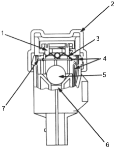
- 1. RESET BUTTON
- 2. BOOT
- 3. SPRING
- 4. TERMINALS
- 5. STEEL BALL
- 6. MAGNET
- 7. MOVING CONTACT
PDF p. 422 · 11-92
PGM-FI Main Relay
Description
The PGM-FI main relay actually contains two individual relays. This relay is located at the driver side of the cowl. One relay is energised whenever the ignition is on which supplies the battery voltage to the ECM/PCM, power to the fuel injectors and power for the second relay. The second relay is energised for two seconds when the ignition is switched on and when the engine is running, to supply power to the fuel pump.
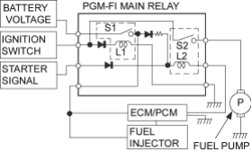
Relay Testing
NOTE: If the engine starts and continues to run, the PGM-FI main relay is OK.
- 1.Remove the PGM-FI main relay.
- 2.Attach the battery positive terminal to the No. 2 terminal and the battery negative terminal to the No. 1 terminal of the PGM-FI main relay. Then check for continuity between the No. 5 terminal and No. 4 terminal of the PGM-FI main relay.
- If there is continuity, go on to step 3.
- If there is no continuity, replace the PGM-FI main relay and retest.
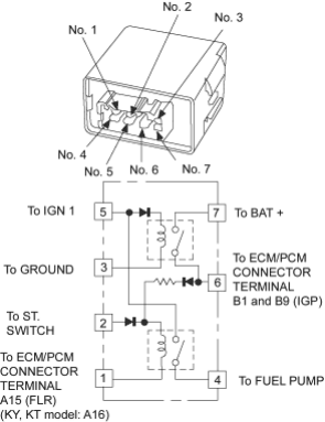
- 3.Attach the battery positive terminal to the No. 5 terminal and the battery negative terminal to the No. 3 terminal of the PGM-FI main relay. Then check that there is continuity between the No. 7 terminal and No. 6 terminal of the PGM-FI main relay.
- If there is continuity, go on to step 4.
- If there is no continuity, replace the PGM-FI main relay and retest.
- 4.Attach the battery positive terminal to the No. 6 terminal and the battery negative terminal to the No. 1 terminal of the PGM-FI main relay. Then check that there is continuity between the No. 5 terminal and No. 4 terminal of the PGM-FI main relay.
- If there is continuity, the PGM-FI main relay is OK.
- If there is no continuity, replace the PGM-FI main relay and retest.
PDF p. 423 · 11-93
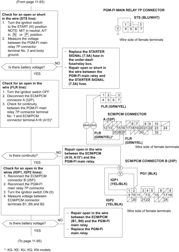
Troubleshooting
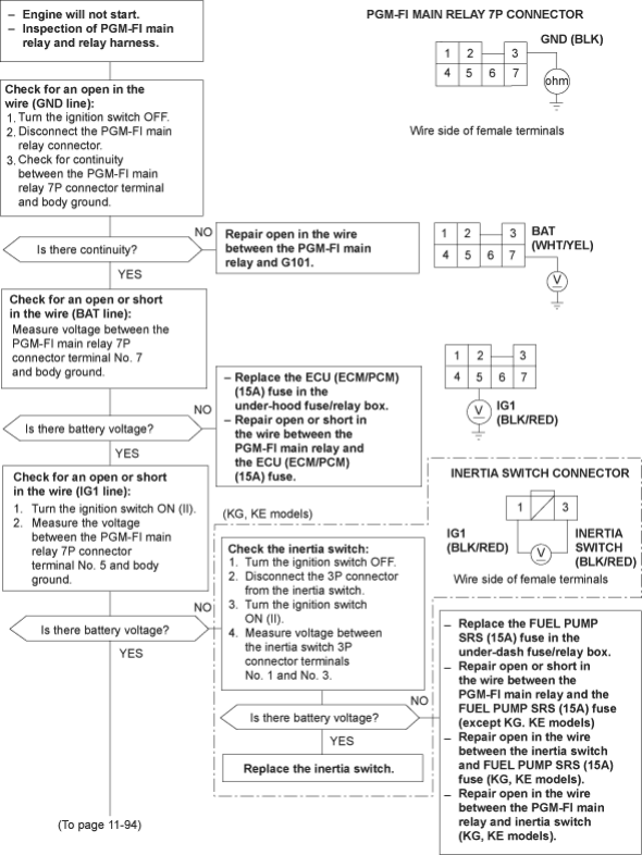
PDF p. 424 · 11-94
PDF p. 425 · 11-95
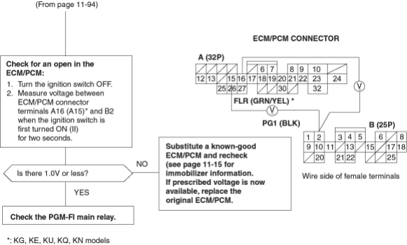
To go to the page referenced on the diagram above, click on the following:
(See Page 11-15)
PDF p. 426 · 11-96
Fuel Tank
Replacement
- 1.Relieve the fuel pressure (See Page 11-80).
- 2.Drain the fuel into an approved container with hand pump.
- 3.Jack up the vehicle and support it with jackstands.
- 4.Remove the fuel tank guard pipe.
- 5.Remove the access panel and disconnect the 5P connector from the fuel tank.
- 6.Disconnect the fuel return hose and quick-connect fittings (See Page 11-77).
- 7.
Disconnect the filler neck connecting hose and fuel breather hose.
NOTE: When disconnecting the hoses, slide back the clamps, then twist hoses as you pull, to avoid damaging them. Disconnect the fuel vapour tube from the EVAP two way valve.
- 8.Place a jack, or other support, under the tank.
- 9.Remove the mount bolt.
- 10.Remove the fuel tank. If it sticks on the undercoat applied to its mount, carefully pry it off the mount.
- 11.Install parts in the reverse order of removal. Clean the flared joint of high pressure hoses thoroughly before reconnecting them.
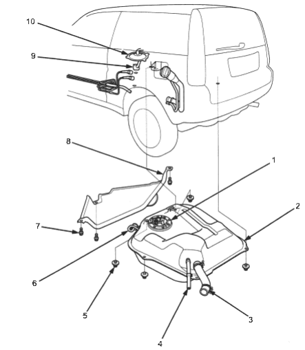
- 1. FUEL PUMP
- 2. FUEL TANK
- 3. FILLER NECK CONNECTING HOSE
- 4. FUEL BREATHER HOSE
- 5. 22 Nm (2.2 kgf/m, 16 lbf/ft)
- 6. EVAP TWO WAY VALVE
- 7. 22 Nm (2.2 kgf/m, 16 lbf/ft)
- 8. FUEL TANK GUARD PIPE
- 9. 5P CONNECTOR
- 10. ACCESS PANEL