PDF p. 352 · 11-24
System Description
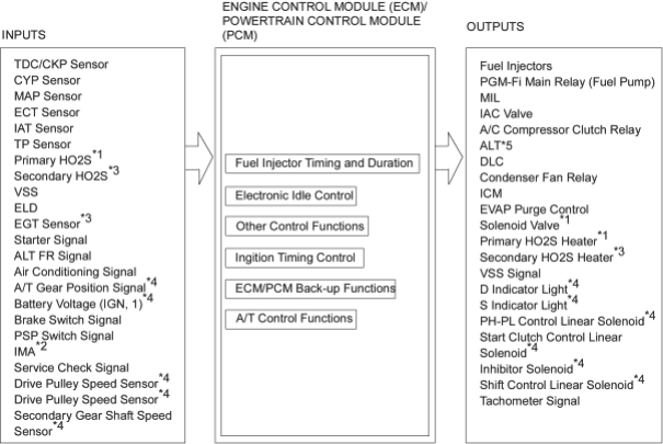
- *1: with TWC models
- *2: without TWC models
- *3: with TWC models except KU model
- *4: A/T
- *5: KG, KE, KQ, KU models
PGM-FI System
The PGM-FI system on this model is a sequential multiport fuel injection system.
Fuel Injector Timing and Duration
The ECM/PCM contains memories for the basic discharge durations at various engine speeds and manifold pressures. The basic discharge duration, after being read out from the memory, is further modified by signals sent from various sensors to obtain the final discharge duration.
Idle Air Control
When the engine is cold, the A/C compressor is on, the transmission is in gear*4, the brake pedal is depressed *5, the P/S load is high, or the alternator is charging, the ECM/PCM controls current to the IAC Valve to maintain the correct idle speed.
Ignition Timing Control
- The ECM/PCM contains memories for basic ignition timing at various engine speeds and manifold air flow rates. Ignition timing is also adjusted for engine coolant temperature.
PDF p. 353 · 11-25
Other Control Functions
- 1.
Starting Control
When the engine is started, the ECM/PCM provides a rich mixture by increasing fuel injector duration.
- 2.Fuel Pump Control
- When the ignition switch is initially turned ON (II), the ECM/PCM supplies ground to the PGM-FI main relay that supplies current to the fuel pump for two seconds to pressurise the fuel system.
- When the engine is running, the ECM/PCM supplies ground to the PGM-FI may relay that supplies current to the fuel pump.
- When the engine is not running and the ignition is ON (II), the ECM/PCM cuts ground to the PGM-FI main relay which cuts current to the fuel pump.
- 3.Fuel Cut-off Control
- During deceleration with the throttle valve closed, current to the fuel injectors is cut off to improve fuel economy at speeds over 1,100 rpm (min-1).
- Fuel cut-off actin also takes place when engine speed exceeds, 6,900 rpm (min-1), regardless of the position of the throttle valve, to protect the engine from over-revving. With A/T model, when the vehicle stops, the ECM/PCM cuts the fuel at engine speed over 5,000 rpm (min-1).
- 4.
A/C Compressor Clutch Relay
When the ECM/PCM receives a demand for cooling from the air conditioning system, it delays the compressor from being energised and enriches the mixture to assure smooth transition to the A/C mode.
- 5.
Alternator Control *5
The system controls the voltage generated at the alternator in accordance with the electrical load and driving mode, which reduces the engine load to improve the fuel economy.
- 6.
Evaporative Emission (EVAP) Purge Control Solenoid Valve*1
When the engine coolant temperature is below 74°C (165°F), the ECM/PCM supplies a ground to the EVAP purge control solenoid valve which cuts vacuum to the EVAP purge control canister.
ECM/PCM Fail-safe/Back-up Functions
- 1.
Fail-safe Function
When an abnormality occurs in a signal from a sensor, the ECM/PCM ignores that signal and assumes a pre-programmed value for that sensor that allows the engine to continue to run.
- 2.
Back-up Function
When an abnormality occurs in the ECM/PCM itself, the fuel injectors are controlled by a back-up circuit independent of the system in order to permit minimal driving.
- 3.
Self-diagnosis Function (Malfunction Indicator Lamp (MIL))
When an abnormality occurs in a signal from a sensor, the ECM/PCM supplies ground for the MIL and stores the code in erasable memory. When the ignition is initially turned ON (II), the ECM/PCM supplies ground for the MIL for two seconds to check the MIL bulb conditions.
PDF p. 354 · 11-26
How to Read Flowcharts
A flowchart is designed to be used from start to final repair. It’s like a map showing you the shortest distance. But beware: if you go off the “map” anywhere but a “stop” symbol, you can easily get lost.

Describes the conditions or situation to start a troubleshooting flowchart.

Asks you to do something; perform a test, set up a condition etc.

Asks you about the result of an action, then sends you in the appropriate troubleshooting direction.

The end of a series of actions and decisions, describes a final repair action and sometimes directs you to an earlier part of the flowchart to confirm your repair.
NOTE:
- The term “Intermittent Failure” is used in these charts. It simply means a system may have had a failure, but it checks out OK at this time. If the Malfunction Indicator Lamp (MIL) on the dash does not come on, check for poor connections or loose wires at all connectors related to the circuit that you are troubleshooting (see illustration below).
- Most of the troubleshooting flowcharts have you reset the Engine Control Module (ECM/Powertrain Control Module (PCM) and try to duplicate the Diagnostic Trouble Code (DTC). If the problem is intermittent and you cannot duplicate the code, do not continue through the flowchart. To do so will only result in confusion and, possibly, a needlessly replaced ECM/PCM.
- “pen” and “Short” are common electrical terms. An open is a break in a wire or at a connection. A short is an accidental connection of a wire to ground or to another wire. In simple electronics, this usually means something works, but not the way it is supposed to.
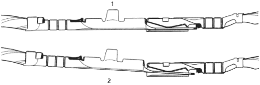
- 1. TIGHT
- 2. LOOSE
PDF p. 355 · 11-27
Engine/Powertrain Control Module (ECM/PCM)
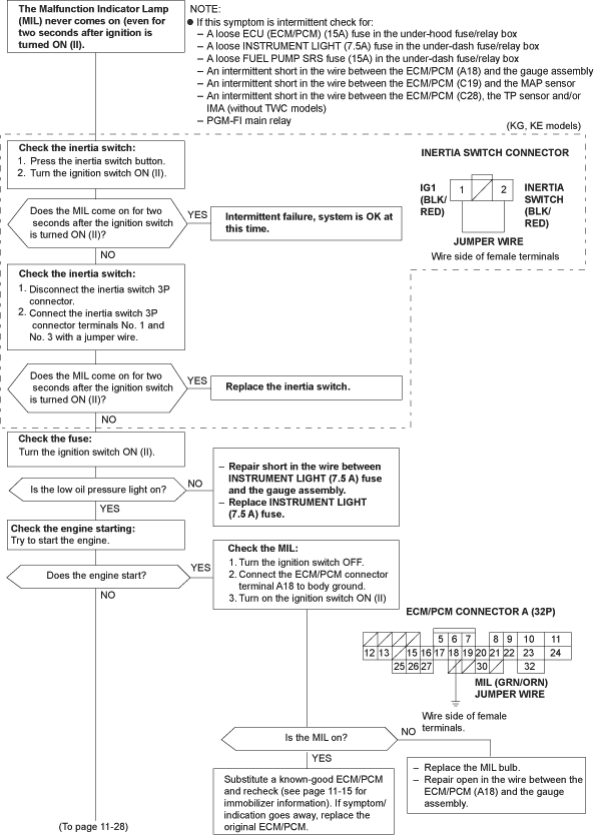
To go to the page referenced on the diagram above, click on the following:
(See Page 11-15)
PDF p. 356 · 11-28
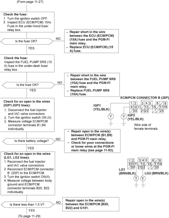
To go to the page referenced on the diagram above, click on the following:
(See Page 11-93)
PDF p. 357 · 11-29
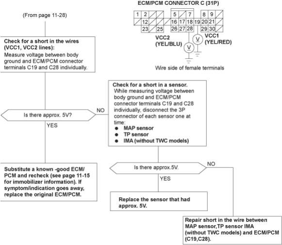
To go to the page referenced on the diagram above, click on the following:
(See Page 11-15)
PDF p. 358 · 11-30
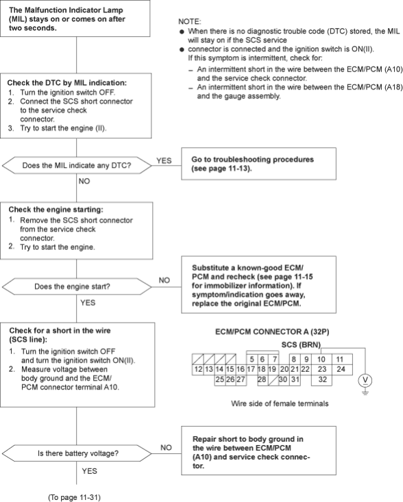
To go to the pages referenced on the diagram above, click on the following:
(See Page 11-13)
(See Page 11-15)
PDF p. 359 · 11-31
PDF p. 360 · 11-32
Primary Heated Oxygen Sensor (Primary HO2S) (with TWC models
1
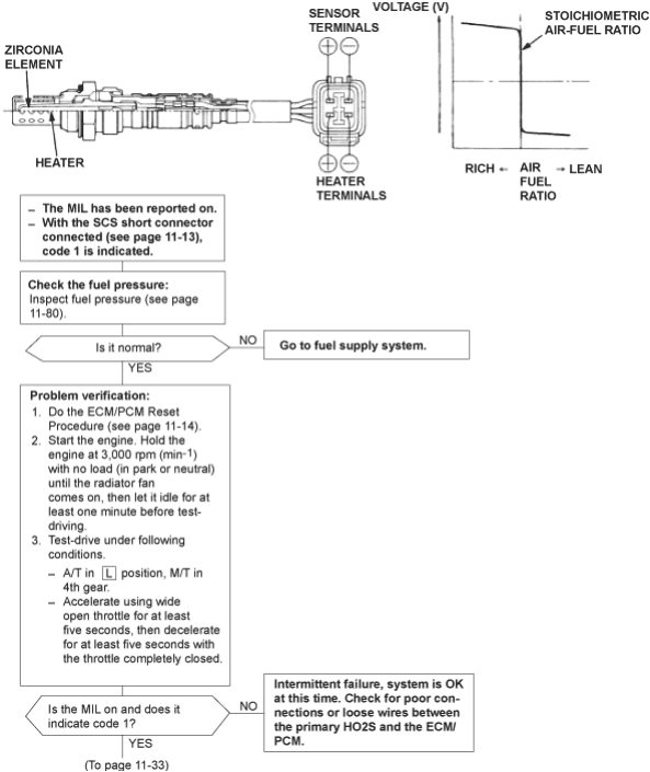
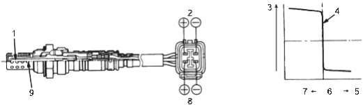
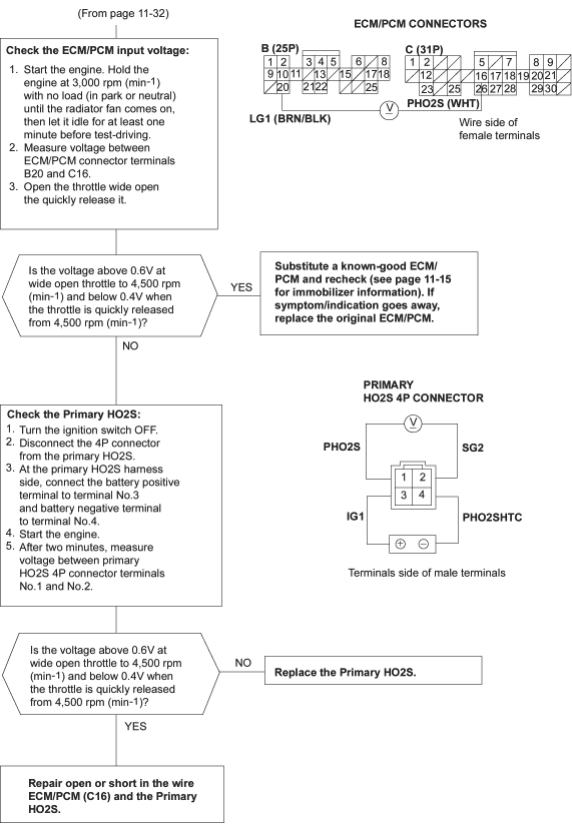
The Malfunction Indicator Lamp (MIL) indicates Diagnostic Trouble Code (DTC) 1: A problem in the Primary Heated Oxygen Sensor (HO2S) circuit.
The Primary Heated Oxygen Sensor (HO2S) detects the oxygen content in the exhaust gas and signals the ECM/PCM in operation, the ECM/PCM receives the signals from the sensor and varies the duration during which fuel is injected. To stabilise the sensor’s output, the sensor has an internal heater. The Primary HO2S is installed in the exhaust manifold.
To go to the pages referenced on the diagram above, click on the following:
(See Page 11-13)
(See Page 11-80)
(See Page 11-14)
PDF p. 361 · 11-33
To go to the page referenced on the diagram above, click on the following:
(See Page 11-15)
PDF p. 362 · 11-34
Manifold Absolute Pressure (MAP) Sensor
3
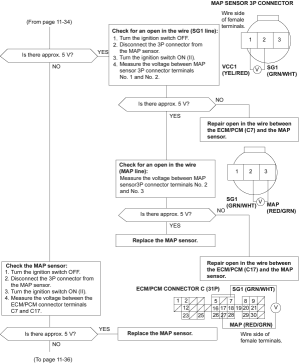
The Malfunction Indicator Lamp (MIL) indicates Diagnostic Trouble Code (DTC) 3: An electrical problem in the Manifold Absolute Pressure (MAP) Sensor circuit.
The MAP sensor converts manifold absolute pressure into electrical signals and inputs the ECM/PCM.
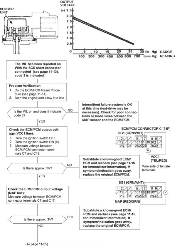
- 1. SENSOR
- 2. OUTPUT VOLTAGE
- 3. GAUGE
- 4. READING
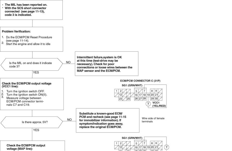

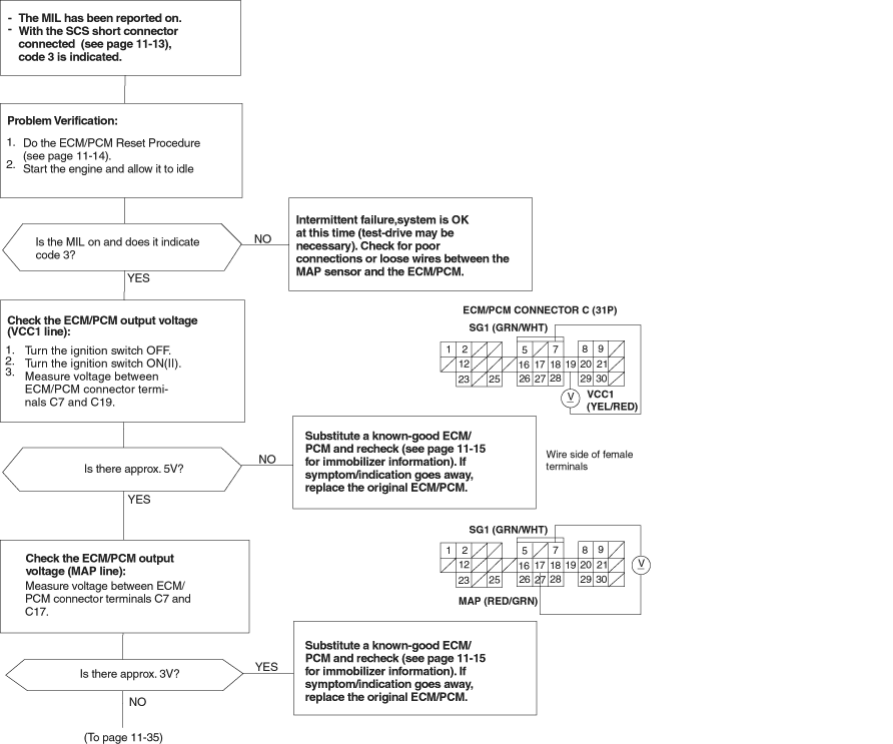
To go to the pages referenced on the diagram above, click on the following:
(See Page 11-13)
(See Page 11-14)
(See Page 11-15)
PDF p. 364 · 11-35
PDF p. 365 · 11-36
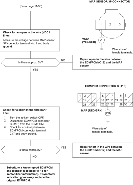
To go to the page referenced on the diagram above, click on the following:
(See Page 11-15)
PDF p. 366 · 11-37
CKP/TDC/CYP Sensor
4
The Malfunction Indicator Lamp (MIL) indicates Diagnostic Trouble Code (DTC) 4: A problem in the Crankshaft Position (CKP) sensor circuit.
8
The Malfunction Indicator Lamp (MIL) indicates Diagnostic Trouble Code (DTC) 8: A problem in the Top Dead Centre (TDC) sensor circuit.
9
The Malfunction Indicator Lamp (MIL) indicates Diagnostic Trouble Code (DTC) 9: A problem in the Cylinder Position (CYP) sensor circuit.
The CKP Sensor determines timing or fuel injection and ignition of each cylinder and also detects engine speed. The TDC Sensor determines ignition timing at start-up (cranking) and when crank angle is abnormal. The CYP Sensor detects the position of No.1 cylinder for sequential fuel injection to each cylinder. The TDC/CKP/CYP Sensor is built into the distributor.
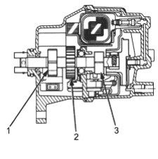
- 1. TDC SENSOR ROTOR
- 2. CKP SENSOR ROTOR
- 3. CYP SENSOR ROTOR
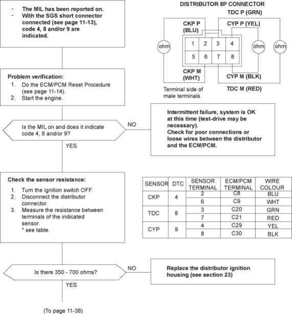
To go to the pages referenced on the diagram above, click on the following:
(See Page 11-13)
(See Page 11-14)
PDF p. 367 · 11-38
CKP/TDC/CTP Sensor
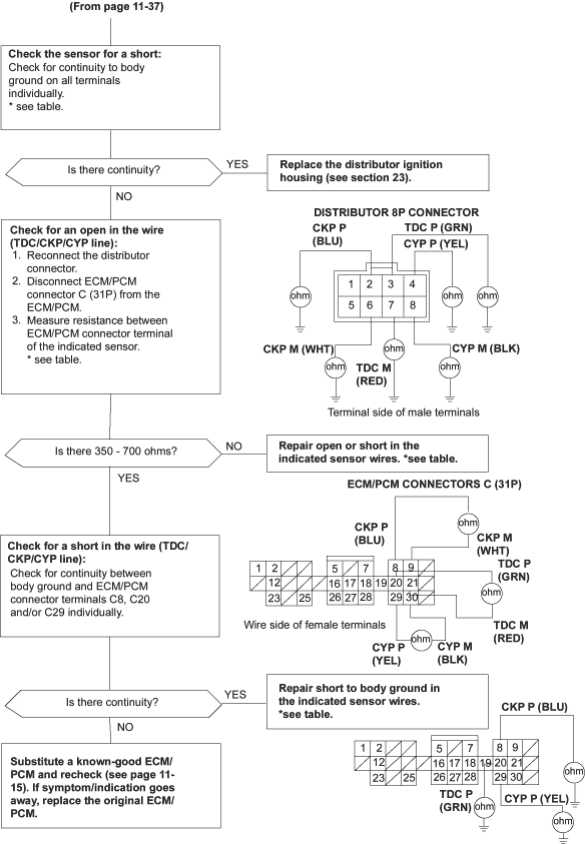
To go to the page referenced on the diagram above, click on the following:
(See Page 11-15)
PDF p. 368 · 11-39
Engine Coolant Temperature (ECT) Sensor
6
The Malfunction Indicator Lamp (MIL) indicates Diagnostic Trouble Code (DTC) 6: A problem in the Engine Coolant Temperature (ECT) sensor circuit.
The ECT Sensor is a temperature dependant resistor (thermistor). The resistance of the thermistor decreases as the engine coolant temperature increases as shown below:
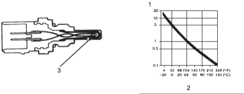
- 1. RESISTANCE (k ohm)
- 2. ENGINE COOLANT TEMPERATURE
- 3. THERMISTOR
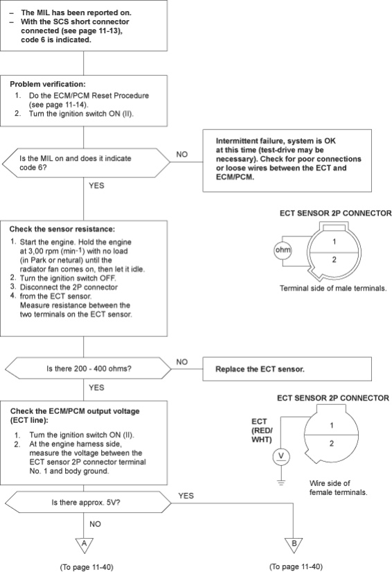
To go to the pages referenced on the diagram above, click on the following:
(See Page 11-13)
(See Page 11-14)
PDF p. 369 · 11-40
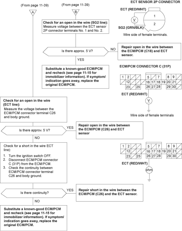
To go to the page referenced on the diagram above, click on the following:
(See Page 11-15)
PDF p. 370 · 11-41
Throttle Position (TP) Sensor
7
The Malfunction Indicator Lamp (MIL) indicates Diagnostic Trouble Code (DTC) 7: A problem in the Throttle Position (TP) sensor circuit.
The TP Sensor is a potentiometer. It is connected to the throttle valve shaft. As the throttle position changes, the throttle position sensor varies the voltage signal to the ECM/PCM.
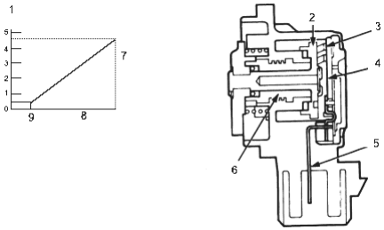
- 1. OUTPUT VOLTAGE (V)
- 2. BRUSH HOLDER
- 3. BRUSH
- 4. RESISTOR
- 5. TERMINAL
- 6. INNER BUSH
- 7. THROTTLE OPENING
- 8. FULL THROTTLE
- 9. IDLE
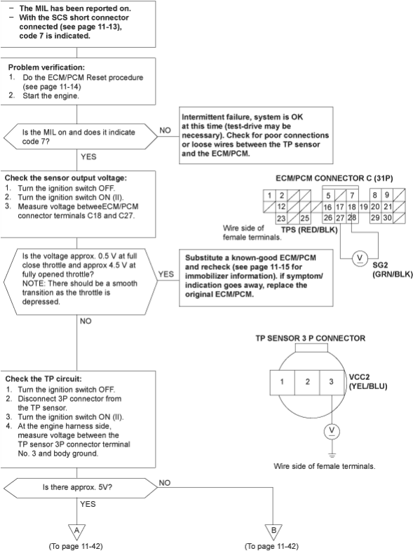
To go to the pages referenced on the diagram above, click on the following:
(See Page 11-13)
(See Page 11-14)
(See Page 11-15)
PDF p. 371 · 11-42
Throttle Position (TP) Sensor (cont’d(
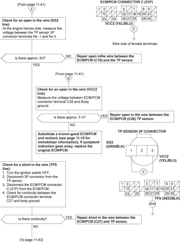
To go to the page referenced on the diagram above, click on the following:
(See Page 11-15)
PDF p. 372 · 11-43
Throttle Position (TP) Sensor
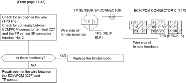
PDF p. 373 · 11-44
Intake Air Temperature (IAT) Sensor
10
The Malfunction Indicator Lamp (MIL) indicates Diagnostic Trouble Code (DTC) 10: A problem in the Intake Air Temperature (IAT) sensor circuit.
The IAT sensor is a temperature dependant resistor (thermistor). The resistance of the thermistor decreases as the intake air temperature increases as shown below:
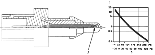
- 1. RESISTANCE (k ohm)
- 2. INTAKE AIR TEMPERATURE
- 3. THERMISTOR
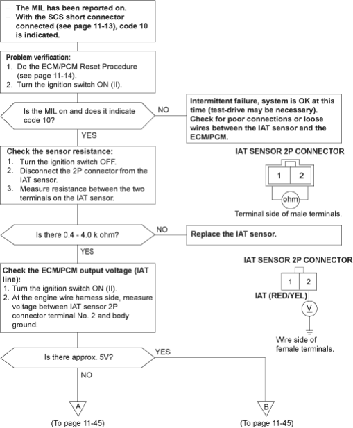
To go to the pages referenced on the diagram above, click on the following:
(See Page 11-13)
(See Page 11-14)
PDF p. 374 · 11-45
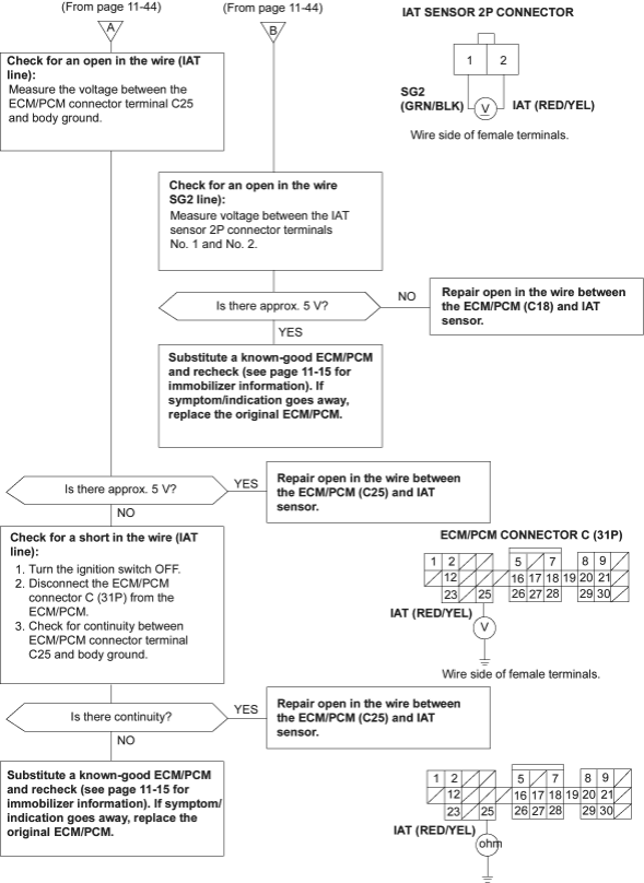
To go to the page referenced on the diagram above, click on the following:
(See Page 11-15)
PDF p. 375 · 11-46
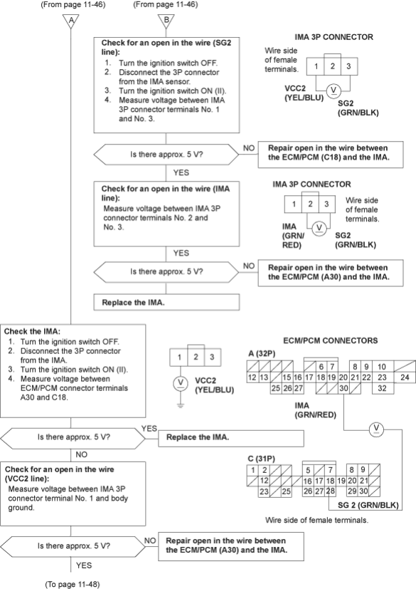
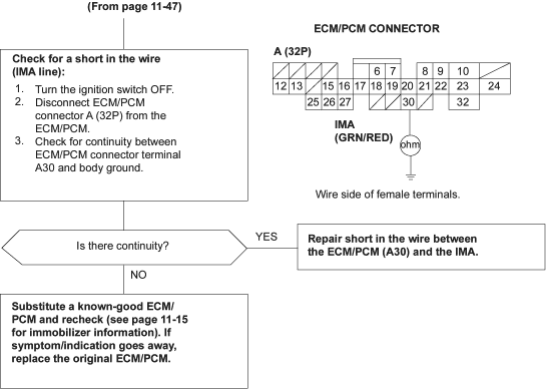
Idle Mixture Adjuster (IMA) (without TWC models)
11
The Malfunction Indicator Lamp (MIL) indicates Diagnostic Trouble Code (DTC) 11: A problem in the Idle Mixture Adjuster (IMA) circuit.
The idle Mixture Adjuster (IMA) is selected resistance device used to control idle mixture.
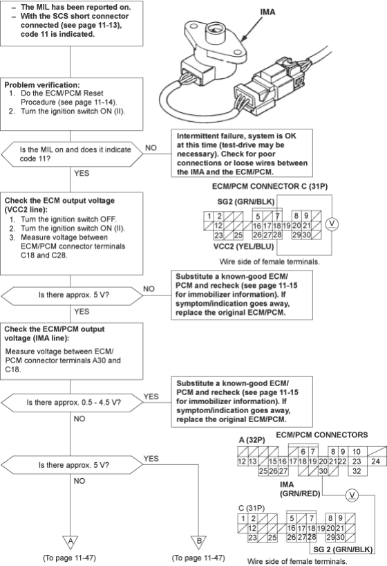
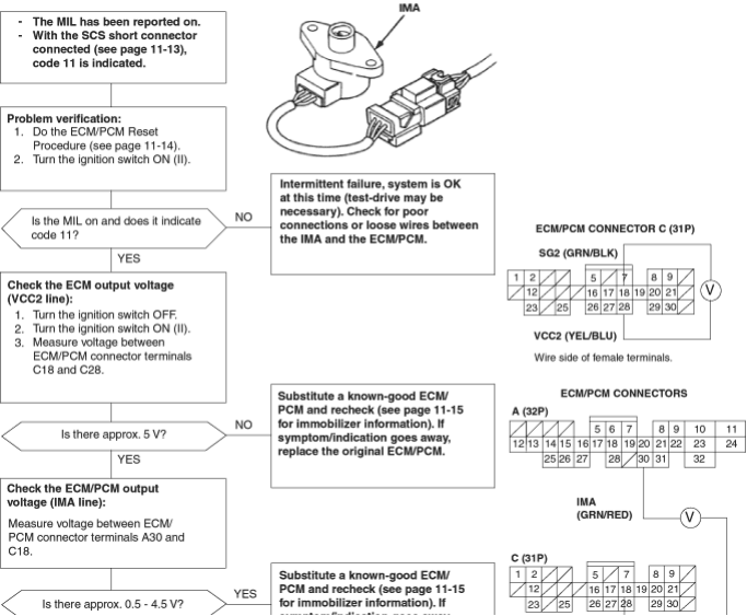
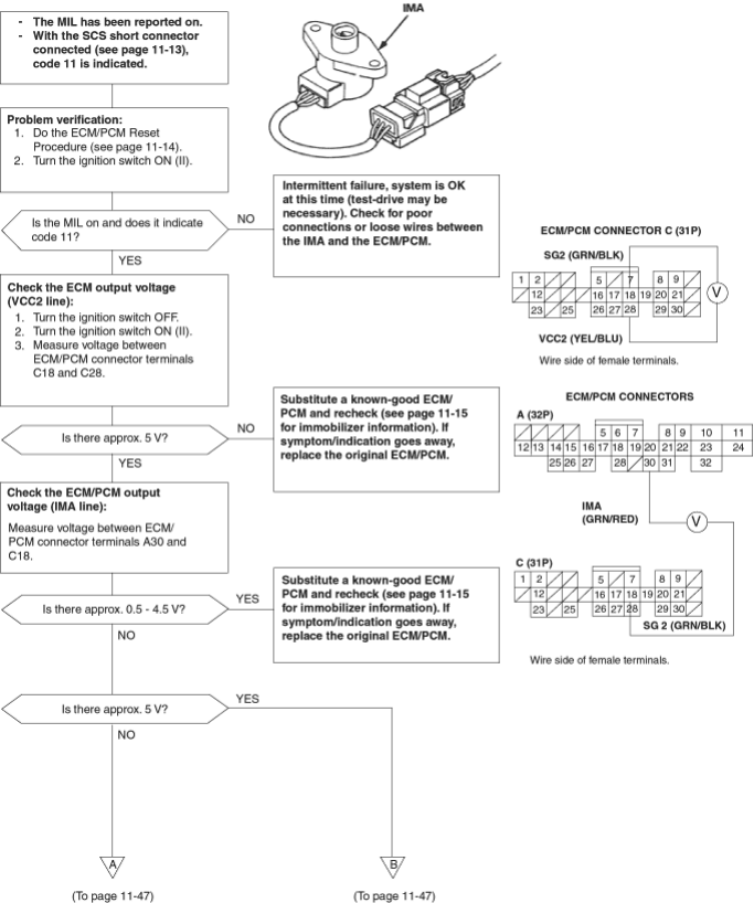
To go to the pages referenced on the diagram above, click on the following:
(See Page 11-13)
(See Page 11-14)
(See Page 11-15)
PDF p. 377 · 11-47
PDF p. 378 · 11-48
To go to the page referenced on the diagram above, click on the following:
(See Page 11-15)
PDF p. 379 · 11-49
Vehicle Speed Sensor (VSS)
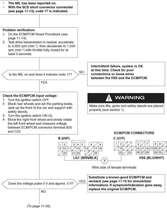
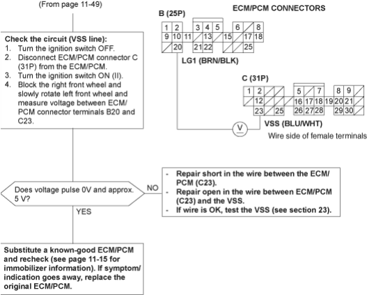
17
The Malfunction Indicator Lamp (MIL) indicates Diagnostic Trouble Code (DTC) 17: A problem in the Vehicle Speed Sensor (VSS) circuit.
The VSS generates a pulsing signal when the front wheels turn.
To go to the pages referenced on the diagram above, click on the following:
(See Page 11-13)
(See Page 11-14)
(See Page 11-15)
PDF p. 380 · 11-50
To go to the page referenced on the diagram above, click on the following:
(See Page 11-15)
PDF p. 381 · 11-51
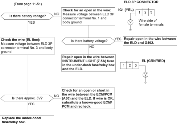
Electrical Load Detector (ELD) (KG, KE, KU, KQ models)
20
The Malfunction Indicator Lamp (MIL) indicates Diagnostic Trouble Code (DTC) 20: A problem in the Electrical Load Detector (ELD) circuit.
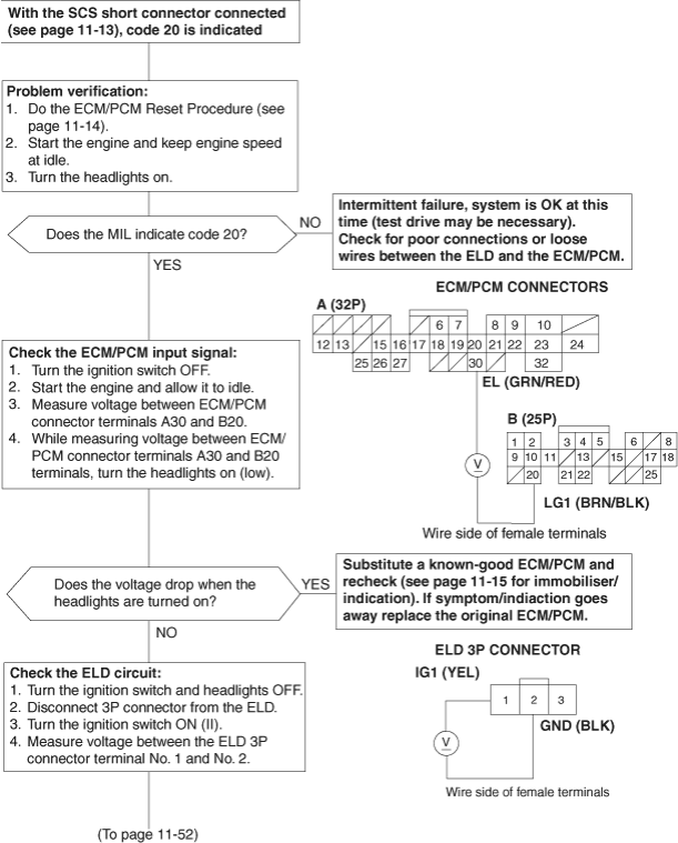
To go to the pages referenced on the diagram above, click on the following:
(See Page 11-13)
(See Page 11-14)
(See Page 11-15)
PDF p. 382 · 11-52
PDF p. 383 · 11-53
Heated Oxygen Sensor (HO2S) Heater (with TWC models)
41
The Malfunction Indicator Lamp (MIL) indicates Diagnostic Trouble Code (DTC) 41: A problem in the Primary Heated Oxygen Sensor (HO2S) heater circuit.
65
The Malfunction Indicator Lamp (MIL) indicates Diagnostic Trouble Code (DTC) 65: A problem in the Secondary Heated Oxygen Sensor (HO2S) heater circuit (with
TWC models except KU model.
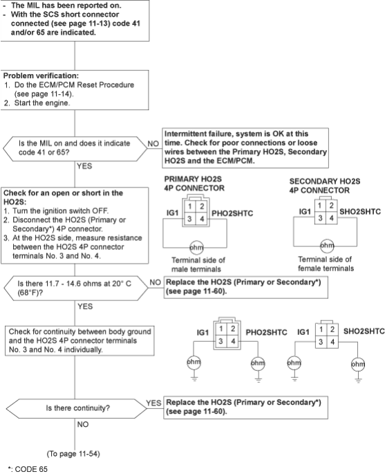
To go to the pages referenced on the diagram above, click on the following:
(See Page 11-13)
(See Page 11-14)
(See Page 11-60)
PDF p. 384 · 11-54
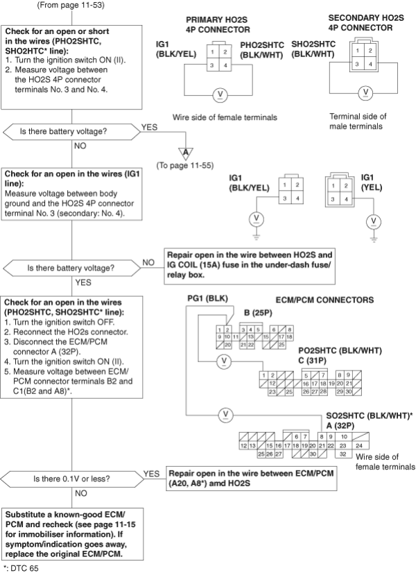
To go to the page referenced on the diagram above, click on the following:
(See Page 11-15)
PDF p. 385 · 11-55
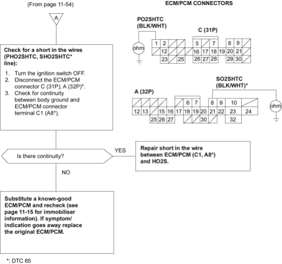
To go to the page referenced on the diagram above, click on the following:
(See Page 11-15)
PDF p. 386 · 11-56
Exhaust Gas Temperature (EGT) Sensor (with TWC model (except KU model)
55
The Malfunction Indicator Lamp (MIL) indicates Diagnostic Trouble Code (DTC) 55: A problem in the Exhaust Gas Temperature (EGT) Sensor circuit.
The EGT sensor is a temperature dependant resistor (thermistor). The resistance of the thermistor decreases as the exhaust gas temperature increases.
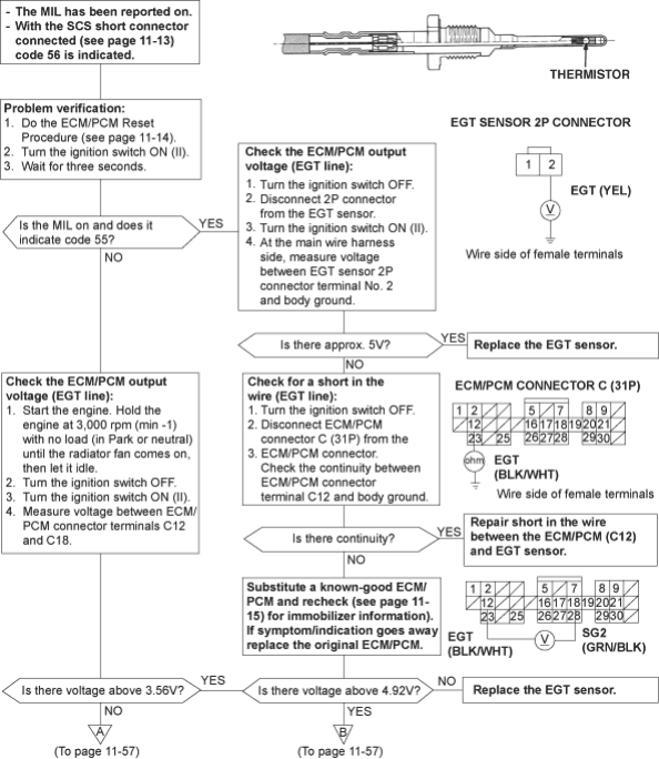
To go to the pages referenced on the diagram above, click on the following:
(See Page 11-13)
(See Page 11-14)
(See Page 11-15)
PDF p. 387 · 11-57
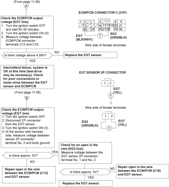
PDF p. 388 · 11-58
Heated Oxygen Sensor (HO2S) Heater (with TWC model) (except KU model)
63
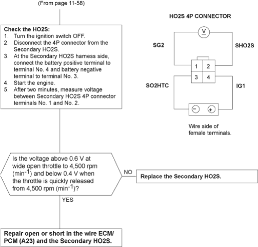
The Malfunction Indicator Lamp (MIL) indicates Diagnostic Trouble Code (DTC) 63: A problem in the Secondary Heated Oxygen Sensor (HO2S) heater circuit.
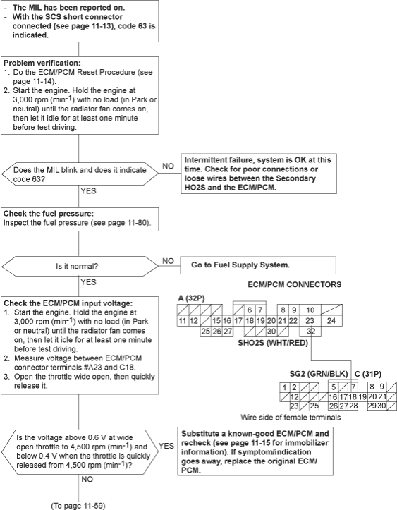
To go to the pages referenced on the diagram above, click on the following:
(See Page 11-13)
(See Page 11-14)
(See Page 11-15)
(See Page 11-80)
PDF p. 389 · 11-59