PDF p. 340 · 11-13
Troubleshooting Procedures)
How To Begin Troubleshooting
When the Malfunction indicator Lamp (MIL) has been reported on, check the Diagnostic Trouble Code (DTC) as follows:
NOTE: This operation can also be carried out with Honda PGM Tester connected to data link connector (5P)).
- 1.Connect the SCS short connector to Service Check Connector as shown (The 2P Service Check Connector is located under the dash on the passenger side of the car). Turn the ignition switch ON (II).
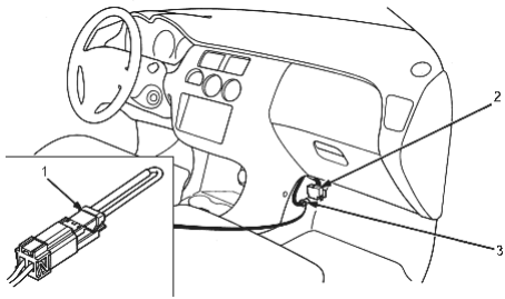
- 1. SCS SHORT CONNECTOR, 07PAZ-0010100
- 2. DATA LINK CONNECTOR (3P)
- 3. SERVICE CHECK CONNECTOR (2P)
The illustration shows LHD type, RHD type is symmetrical
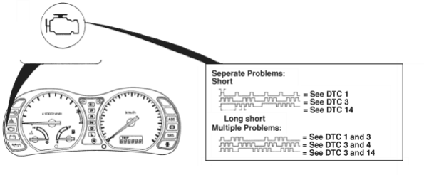
- 2.Note the Diagnostic Trouble Code (DTC); The MIL indicates a code by the length and number of blinks. The MIL can indicate multiple problems by blinking separate codes, one after another. Codes 1 through to 9 are indicated by individual short blinks. Codes 10 through to 65 are indicated by a series of long and short blinks. The number of long blinks equals the first digit, the number of short blinks equals the second digit. Sometimes the first blink is difficult to see; always count the blinks at least twice to verify the code. MALFUNCTION INDICATOR LAMP (MIL)
PDF p. 341 · 11-14
Engine/Powertrain Control Module (ECM/PCM) Reset Procedure
NOTE: This operation can also be carried out with Honda PGM Tester.
- 1.Turn the ignition switch off.
- 2.Remove the BACK UP (7.5 A) fuse from the under-dash fuse/relay box for 10 seconds to reset the ECM/PCM.
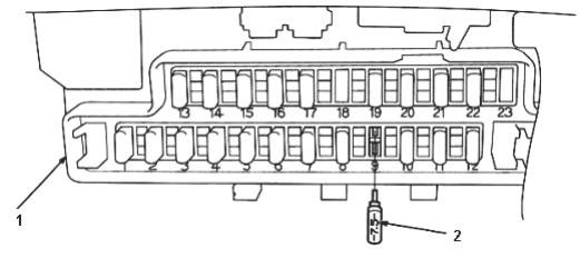
The illustration shows LHD type, RHD type is symmetrical
Final Procedure (this procedure must be done after any troubleshooting)
- 1.Remove the SCS Short Connector
- 1.UNDER-DASH FUSE/RELAY BOX
- 2.BACK UP (7.5 A) FUSE
NOTE: If the SCS short connector is connected and there are not DTCs stored in the ECM/PCM, the MIL will stay on when the ignition switch is turned ON (II).
- 2.Do the ECM/PCM Reset Procedure.
PDF p. 342 · 11-15
Known-Good ECM/PCM Substitution (KG, KE, KQ, KU, KN models)
Use the following procedure if you need a known-good ECM/PCM to test a vehicle. It allows you to swap an ECM/PCM from a “donor” vehicle without having to program it to the test vehicle’s ignition key.
- 1.Cut a temporary ignition key for the test vehicle with a non-immobiliser key blank.
- 2.Remove the ECM/PCM from the test vehicle.
- 3.Write the test vehicle’s VIN on the ECM/PCM you just removed to avoid confusing it with the donor vehicle’s ECM/PCM.
- 4.Remove the known-good ECM/PCM from the donor vehicle and install it in the test vehicle.
- 5.Tape the donor vehicle’s ignition key head-to-head to the test vehicle’s temporary key. The ECM/PCM will recognise the code from the donor vehicle’s key and allow you to start the engine with the temporary key.
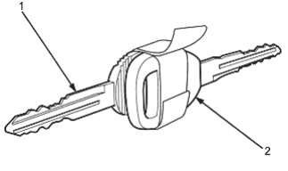
- 1. TEMPORARY KEY
- 2. DONOR KEY
- 6.After completing your tests, reinstall both ECM/PCMs and destroy the temporary key.
ECM/PCM Removal
If the inspection for a particular code requires voltage or resistance checks at the ECM/PCM connectors, remove the glove box, the passenger’s door sill moulding and kick panel. Unbolt the ECM/PCM cover. Check the system according to the procedure described for the appropriate DTC listed on the following pages.
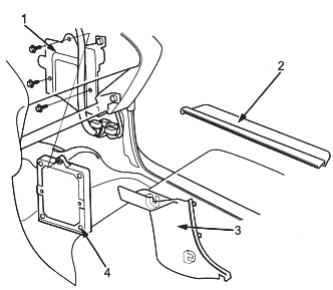
- 1. ECM/PCM COVER
- 2. DOOR SILL MOULDING
- 3. KICK PANEL
- 4. ECM/PCM
The illustration shows LHD type, RHD type is symmetrical
PDF p. 343 · 11-16
Checking The ECM/PCM Connector Terminals
When checking the ECM/PCM connector terminals, gently slide the sharp tester probe from the wire side into the connector until it comes in contact with the terminal end of the wire.
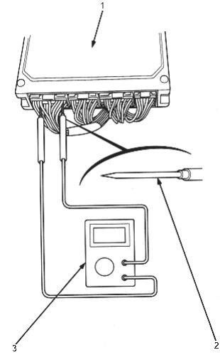
- 1. ECM/PCM
- 2. SHARP TESTER PROBE
- 3. DIGITAL CIRCUIT TESTER Commercially available or 07411-0020000
PDF p. 344 · 11-17
Troubleshooting Guide
NOTE: Across each row in the chart, the systems that could be sources of a symptom are ranked in the order they should be inspected starting with 1. Find the symptom in the left column, read across to the most likely source, then refer to the page listed at the tope of that column. If inspection shows the system is OK, try the next most likely system 2. etc.
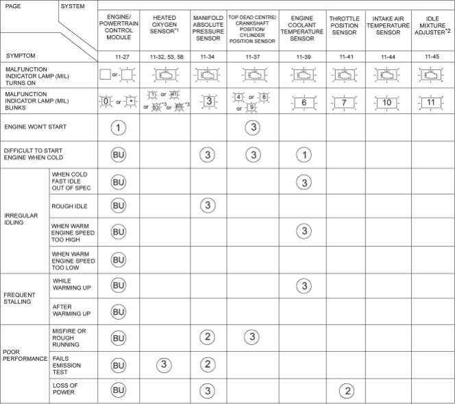
To go to the pages referenced on the diagram above, click on the following:
(See Page 11-27)
(See Page 11-32)
(See Page 11-53)
(See Page 11-58)
(See Page 11-34)
(See Page 11-37)
(See Page 11-39)
(See Page 11-41)
(See Page 11-44)
(See Page 11-46)
* : If codes other than those listed above are indicated, count the number of blinks again. If the MIL is in fact blinking these codes, replace the ECM/PCM.
BU If the MIL is on while the engine is running, connect the SCS short connector to the service check connector. If no code is displayed (MIL stays on steady), the back-up system is
in operation.
Substitute a known-good ECM/PCM and recheck. If the indication goes way, replace the original ECM/PCM.
- *1: with TWC models
- *2: without TWC models
- *3: with TWC models except KU model
PDF p. 345 · 11-18
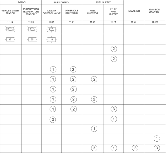
To go to the pages referenced on the diagram above, click on the following:
(See Page 11-49)
(See Page 11-56)
(See Page 11-63)
(See Page 11-61)
(See Page 11-81)
(See Page 11-74)
(See Page 11-97)
(See Page 11-103)
PDF p. 346 · 11-19
Engine/Powertrain Control Module Terminal Arrangement
ECM CONNECTOR A (32P)
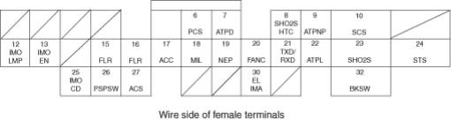
NOTE: Standard battery voltage is 12V.
| Terminal | Wire Colour | Terminal Name | Description | Signal |
|---|---|---|---|---|
| No. | ||||
| 6 *1 | RED | PCS (EVAP purge | Drives EVAP purge | With engine running, engine coolant |
| control solenoid valve) | control solenoid valve. | below 74°C (165°F): 0V: | ||
| With engine running, engine coolant | ||||
| above 74°C (165°F): Battery voltage | ||||
| 7*4 | GRN | ATPD (at gear position | Detects A/T gear | In D position 0V |
| switch) | position switch signal. | In any other position: about 5V | ||
| 8*3 | BLK/WHT | SO2SHTC (Secondary | Drives secondary heated | With ignition ON (II): Battery voltage |
| heated oxygen sensor | oxygen sensor heater | With fully warmed up engine | ||
| heater control) | running: Duty controlled | |||
| 9 *4 | LT/GRN | ATPNP (at gear | Detects A/T gear | In N or P position 0V |
| position switch) | position switch signal | In any other position: Battery voltage | ||
| 10 | BRN | SCS (Service check | Detect service check | With the terminal connected: 0V |
| signal) | connector signal (the | With the terminal disconnected: | ||
| signal causing a DTC | about 5V or Battery voltage | |||
| indication) | ||||
| 12*6 | PNK | IMOLMP (Immobiliser | Drives immobiliser | With immobiliser indicator light |
| indicator light) | indicator light | turned ON: 0V | ||
| With immobiliser indicator light | ||||
| turned OFF: Battery voltage | ||||
| 13*6 | BLU | IMOEN (Immobiliser | Sends immobiliser | |
| enable signal) | enable signal | |||
| 15*6 | GRN/YEL | FLR (Fuel pump relay) | 0V for two seconds after | 0V for two seconds after turning |
| turning ignition switch | ignition switch ON (II), then battery | |||
| ON (II), then battery | voltage | |||
| voltage | ||||
| 16 | GRN/YEL | FLR (Fuel pump relay) | 0V for two seconds after | 0V for two seconds after turning |
| turning ignition switch | ignition switch ON (II), then battery | |||
| ON (II), then battery | voltage | |||
| voltage | ||||
| 17 | BLK/RED | ACC (A/C clutch relay) | Drives A/C clutch relay | With compressor ON: 0V |
| With compressor OFF: Battery | ||||
| voltage | ||||
| 18 | GRN/ORN | MIL (Malfunction | Drives MIL | With MIL turned ON: 0V |
| indication light) | With MIL turned OFF: Battery | |||
| voltage | ||||
| 19 | BLU/BLK | NEP (Engine speed | Outputs engine speed | With engine running: Pulses |
| pulse) | pulse | |||
| 20*5 | GRN | FANC (Radiator fan | Drives radiator fan relay | With radiator fan running: 0V |
| control) | With radiator fan stopped: Battery | |||
| voltage | ||||
| 21 | LT BLU | TXD/RXD (DLC) | Sends and receives | With ignition switch ON (II): 5V |
| Honda PGM Tester | ||||
| signal | ||||
| 22 | BLU | ATPL (At gear position | Detects A/T gear | In L position: 0V |
| switch) | position switch signal | In any other position: Battery voltage | ||
| 23*3 | WHT/RED | SHO2S (Secondary | Detects secondary | With throttle fully opened from idle |
| heated oxygen sensor, | heated oxygen sensor | with fully warmed up engine: Above | ||
| sensor 2) | (sensor 2) signal | 0.6V | ||
| With throttle quickly closed: Below | ||||
| 0.4V | ||||
| 24 | BLU/WHT | STS (Starter switch | Detects starter switch | With starter switch ON (II): Battery |
| signal) | signal | voltage | ||
| With starter switch OFF: 0V | ||||
| 25*6 | RED | IMOCD (Immobiliser | Detects immobiliser | |
| code) | signal | |||
| 26 | GRN | PSPSW (P/S pressure | Detects PSP switch | AT idle with steering wheel in |
| switch signal) | signal | straight ahead position: 0V | ||
| At idle with steering wheel at full | ||||
| lock: Battery voltage | ||||
| 27 | BLU/RED | ACS (A/C switch signal) | Detects A/C switch signal | With A/C switch ON: 0V |
| With A/C switch OFF: Battery | ||||
| voltage | ||||
| 30*5 | ORN/RED | EL (ELD) | Detects ELD signal | With parking lights turned on at idle |
| about 2.5-3.5V | ||||
| With A/C switch OFF: Battery | ||||
| voltage | ||||
| 30 *2 | ORN/RED | IMA (Idle mixture | Detects IMA signal | With ignition switch ON (II): about |
| adjusted) | 0.5-4.5V (depending on idle mixture) | |||
| 32 | GRN/WHT | BKSW (Brake switch) | Detects brake switch | With brake pedal released: 0V |
| PDF p. 347 | ||||
| signal | With brake pedal depressed: | |||
| Battery voltage | ||||
| | | | | |
- *1: with TWC models
- *2: without TWC models
- *3: with TWC models except KU model
- *4: A/T
- *5: KG, KE, KQ, KU models
- *6: KG, KE, KQ, KN, KU models
PDF p. 348 · 11-20
Engine/Powertrain Control Module Terminal Arrangement
ECM/PCM CONNECTOR B (25P)
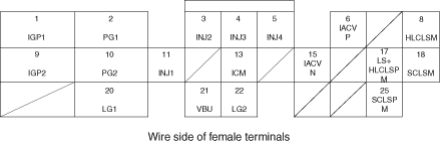
NOTE: Standard battery voltage is 12V.
| Terminal | Wire Colour | Terminal Name | Description | Signal |
|---|---|---|---|---|
| No. | ||||
| 1 | YEL/BLK | IGP1 (Power source) | Power source for the | With ignition switch ON (II): Battery |
| ECM/PCM control circuit | voltage | |||
| With ignition switch OFF: 0V | ||||
| 2 | BLK | PG1 (Power ground) | Ground for the | Less than 1.0V at all times |
| ECM/PCM control circuit | ||||
| 3 | RED | INJ2 (No. 2 fuel | Drives No. 2 fuel injector | With engine running: Duty controlled |
| injector) | ||||
| 4 | BLU | INJ3 (No. 3 fuel | Drives No. 3 fuel injector | With engine running: Duty controlled |
| injector) | ||||
| 5 | YEL | INJ4 (No. 4 fuel | Drives No. 4 fuel injector | With engine running: Duty controlled |
| injector) | ||||
| 6 | BLK/BLU | IACVP (Idle air control | Drives IAC valve | With engine running: Duty controlled |
| valve positive side) | (positive side) | |||
| 8 *4 | PNK/BLK | HLCLSM (PH-PL | PH-PL control linear | With ignition switch ON (II): Duty |
| control linear solenoid | solenoid power supply | controlled | ||
| M side) | negative electrode | |||
| 9 | YEL/BLK | IGP2 (Power source) | Power source for the | With ignition switch ON (II): Battery |
| ECM/PCM control circuit | voltage | |||
| With ignition switch OFF: 0V | ||||
| 10 | BLK | PG2 (Power ground) | Ground for the | Less than 1.0V at all times |
| ECM/PCM control circuit | ||||
| 11 | BRN | INJ1 (No. 1 fuel | Drives No. 1 fuel injector | With engine running: Duty controlled |
| injector) | ||||
| 13 | YEL/GRN | ICM (Ignition control | Sends ignition pulse | With ignition switch ON (II): Battery |
| module) | voltage | |||
| With engine running: Pulses) | ||||
| 15 | GRN | IACVN (Idle air control | Drives IAC valve | With engine running, Duty controlled |
| valve negative side) | (negative side) | |||
| 17 *4 | GRN/WHT | HLCLSP (PH-PL | PH-PL control linear | With ignition switch ON (II): Duty |
| control linear solenoid | solenoid power supply | controlled | ||
| P side) | positive electrode | |||
| 18 *4 | PNK/BLU | SCLSM (Start clutch | Start clutch control linear | With ignition switch ON (II): Duty |
| control linear solenoid | solenoid power supply | controlled | ||
| M side | negative electrode | |||
| 20 | BRN/BLK | LG1 (Logic ground) | Ground for the | Less than 1.0V at all times |
| ECM/PCM control circuit | ||||
| 21 | WHT/BLU | VBU (Voltage back up) | Power source for the | Battery voltage at all times |
| ECM/PCM control circuit | ||||
| Power source for the | ||||
| DTC memory | ||||
| 22 | BRN/BLK | LG2 (Logic ground) | Ground for the | Less than 1.0V at all times |
| ECM/PCM control circuit | ||||
| 25 *4 | YEL | SCLSP (Start clutch | Start clutch control linear | With ignition switch ON (II): Duty |
| control linear solenoid | solenoid power supply | controlled | ||
| P side) | positive electrode |
- *1: with TWC models
- *2: without TWC models
- *3: with TWC models except KU model
- *4: A/T
- *5: KG, KE, KQ, KU models
- *6: KG, KE, KQ KN, KU models
PDF p. 349 · 11-21
ECM/PCM CONNECTOR C (31P)
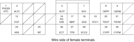
NOTE: Standard battery voltage is 12V.
| Terminal | Wire Colour | Terminal Name | Description | Signal |
|---|---|---|---|---|
| No. | ||||
| 1*1 | BLK/WHT | PO2SHTC (Primary | Drives primary heated | With ignition switch ON (II): Battery |
| heated oxygen sensor | oxygen sensor heater | voltage | ||
| heater control) | With fully warmed up engine | |||
| running: Duty controlled | ||||
| 2*5 | WHT/GRN | ALTC (Alternator | Sends alternator control | With fully warmed up engine |
| control) | signal | running: Battery voltage | ||
| During driving with small electrical | ||||
| load: 0V | ||||
| 5 | WHT/RED | ALTF (Alternator FR | Detects alternator FR | With fully warmed up engine |
| signal) | signal | running: 0V - battery voltage | ||
| (depending on electrical load) | ||||
| 7 | GRN/WHT | SG1 (Sensor ground) | Ground for MAP sensor | Less than 1.0V at all times |
| 8 | BLU | CKPP (CKP sensor P | Detects CKP sensor | With engine running: Pulses |
| side) | ||||
| 9 | WHT | CKPM (CKP sensor M | Ground for CKP sensor | |
| side) | ||||
| 12 | BLK/WHT | EGT (exhaust gas | Detects EGT sensor | With ignition switch ON (II): about |
| temperature sensor)) | signal | 0.1-4.8V (depending on exhaust gas | ||
| temperature) | ||||
| 16*1 | WHT | PHO2S (Primary | Detects primary heated | With throttle fully opened from idle |
| heated oxygen sensor, | oxygen sensor (sensor | with fully warmed up engine: Above | ||
| sensor 1) | 1) signal | 0.6V | ||
| With throttle quickly closed: Below | ||||
| 0.4V | ||||
| 17 | RED/GRN | MAP (Manifold | Detects MAP sensor | With ignition switch ON (II): About 3V |
| absolute pressure | signal | At idle: About 1.0V (depending on | ||
| sensor) | engine speed) | |||
| 18 | GRN/BLK | SG2 (Sensor ground) | Sensor ground | Less than 1.0V at all times |
| 19 | YEL/RED | VCC1 (Sensor voltage) | Power source to MAP | With ignition switch ON (II): About 5V |
| sensor | With ignition switch OFF: 0V | |||
| 20 | GRN | TDCP (TDC sensor P | Detects TDC sensor | With engine running: Pulses |
| side) | ||||
| 21 | RED | TDCM (TDC sensor M | Ground for TDC sensor | |
| side) | ||||
| 23 | BLU/WHT | VSS (Vehicle speed | Detects VSS signal | With ignition switch ON (II) and front |
| sensor) | wheel rotating: Cycles 0V - 5V | |||
| 25 | RED/YEL | IAT (Intake air | Detects IAT sensor | With ignition switch ON (II): About |
| temperature sensor) | signal | 0.1 - 4.8V (depending on intake air | ||
| temperature) | ||||
| 26 | RED/WHT | ECT (Engine coolant | Detects ECT sensor | With ignition switch ON (II): About |
| temperature sensor) | signal | 0.1 - 4.8V (depending on engine | ||
| coolant temperature) | ||||
| 27 | RED/BLK | TPS (Throttle position | Detects TP sensor signal | With throttle fully open: About 4.8V |
| sensor) | With throttle fully closed: About 0.5V | |||
| 28 | YEL/BLU | VCC2 (Sensor voltage) | Provides sensor voltage | With ignition switch ON (II): About 5V |
| With ignition switch OFF: 0V | ||||
| 29 | YEL | CYPP (CYP sensor P | Detects CYP sensor | With engine running: Pulses |
| side) | ||||
| 30 | BLK | CYPM (CYP sensor P | Ground for CYP sensor | |
| side) |
- *1: with TWC models
- *2: without TWC models
- *3: with TWC models except KU model
- *4: A/T
- *5: KG, KE, KQ, KU models
- *6: KG, KE, KQ KN, KU models
PDF p. 350 · 11-22
PCM CONNECTOR D (16P) *4
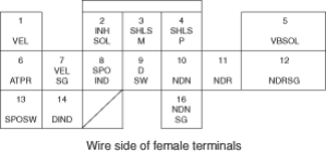
NOTE: Standard battery voltage is 12V.
| Terminal | Wire Colour | Terminal Name | Description | Signal |
|---|---|---|---|---|
| No. | ||||
| 1 | WHT/RED | VEL (Secondary gear | Secondary gear shaft | Depending on vehicle speed: Pulses |
| shaft speed sensor) | speed sensor | When vehicle is stopped: 0V | ||
| 2*4 | GRN/BLK | INHSOL (Inhibitor | Inhibitor solenoid control | With inhibitor solenoid ON: Battery |
| solenoid control) | voltage | |||
| With inhibitor solenoid OFF: 0V | ||||
| 3*4 | GRN/YEL | SHLS M (Shift control | Shift control linear | With ignition switch ON (II): Pulses |
| linear solenoid M side) | solenoid power supply | |||
| negative | ||||
| 4*4 | BLU/WHT | SHLS P (Shift control | Shift control linear | With ignition switch ON (II): Pulses |
| linear solenoid P side) | solenoid power supply | |||
| negative | ||||
| 5*4 | BLK/YEL | VBSOL (Battery | Power source of | With ignition switch ON (II): Battery |
| voltage for solenoid | solenoid valve | voltage | ||
| valve) | With ignition switch OFF: 0V | |||
| 6*4 | WHT | ATPR (At gear position | Detects A/T gear | In R position: 0V |
| switch) | position switch signal | In any other position: Battery voltage | ||
| 7*4 | BLK/WHT | VELSG (Secondary | Ground for secondary | |
| gear shaft speed | gear shaft speed sensor | |||
| sensor ground) | ||||
| 8*4 | LT GRN | SPOIND (S indicator | Drives S indicator | With S indicator turned ON: Battery |
| light) | voltage | |||
| With S indicator turned OFF: 0V | ||||
| 9*4 | BLU | DSW (D mode switch) | Detects D mode switch | With D mode switch ON: 0V |
| signal | With D mode switch OFF: Battery | |||
| Voltage | ||||
| 10*4 | WHT | NDN (Driven pulley | Detects driven pulley | In other than N or P position: Pulses |
| speed sensor) | speed sensor signal | |||
| 11*4 | RED/BLU | NDR (Drive pulley | Detects drive pulley | In other than N or P position: Pulses |
| speed sensor) | speed sensor signal | |||
| 12*4 | GRN | NDRSG (Drive pulley | Ground for drive pulley | |
| speed sensor ground) | speed sensor | |||
| 13*4 | YEL | SPOSW (S mode | Detects S mode switch | With S mode switch ON: 0V |
| switch) | signal | With S mode switch OFF: Battery | ||
| voltage | ||||
| 14*4 | GRN/BLK | DIND (D indicator light) | Drives D indicator | With D indicator turned ON: Battery |
| voltage | ||||
| With D indicator turned OFF: 0V | ||||
| 16 | RED/WHT | NDNSG (Driven pulley | Ground for driven pulley | |
| speed sensor ground) | speed sensor |
- *4: A/T
PDF p. 351 · 11-23
Diagnostic Trouble Code (DTC) Chart
| DIAGNOSTIC | SYSTEM INDICATED | Page |
|---|---|---|
| TROUBLE CODE (DTC) | ||
| 0 | Engine/Powertrain control module (ECM/PCM) | (see |
| page11-27) | ||
| 1 | Primary heated oxygen sensor (Primary HO2S) | (see |
| page11-32) | ||
| 3 | Manifold absolute pressure (MAP) sensor | (see |
| page11-34) | ||
| 4 | Crankshaft position (CKP) sensor | (see |
| page11-37) | ||
| 6 | Engine coolant temperature (ECT) sensor | (see |
| page11-39) | ||
| 7 | Throttle position (TP) sensor | (see |
| page11-41) | ||
| 8 | Top dead centre position (TDC) sensor | (see |
| page11-37) | ||
| 9 | No. 1 Cylinder position (CYP) sensor | (see |
| page11-37) | ||
| 10 | Intake air temperature (IAT) sensor | (see |
| page11-44) | ||
| 11 | Idle mixture adjuster (IMA)*2 | (see |
| page11-46) | ||
| 14 | Idle air control (IAC) valve | (see |
| page11-63) | ||
| 17 | Vehicle speed sensor (VSS) | (see |
| page11-49) | ||
| 41 | Primary heated oxygen sensor (Primary HO2S) heater*1 | (see |
| page11-53) | ||
| 55*3 | Exhaust gas temperature (EGT) sensor | (see |
| page11-56) | ||
| 63 | Secondary heated oxygen sensor (Secondary HO2S)*3 | (see |
| page11-58) | ||
| 65 | Secondary heated oxygen sensor (Secondary HO2S) heater *3 | (see |
| page11-53) | ||
| 70*4 | Automatic transmission | Section 14 |
- *1: with TWC models
- *2: without TWC models
- *3: with TWC models except KU model
- *4: A/T
- If codes other tan those listed above are indicated, verify the code. If the code indicated is not listed above, replace the ECM/PCM (see page 11-15) for immobiliser information.
- The MIL may come on, indicating a system problem when, in fact, there is a poor or intermittent electrical connection. First, check the electrical connections, clean or repair connections if necessary.