PDF p. 436 · 11-106
Description
The evaporative emission controls are designed to minimise the amount of fuel vapour escaping to the atmosphere. The system consists of the following components.
- A.
Evaporative Emission (EVAP) Control Canister
An EVAP control canister is used for the temporary storage of fuel vapour until the fuel vapour can be purged from the EVAP control canister into the engine and burned.
- B.
Vapour Purge Control System
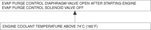
EVAP control canister purging is accomplished by drawing fresh air through the EVAN control canister and into a port on the throttle body. The purging vacuum is controlled by the EVAN purge control diaphragm valve and the EVAN purge control solenoid valve (with TWICE models)
- C.
Fuel Tank Vapour Control System
When fuel vapour pressure in the fuel tank is higher than the set valve of the EVAP two way valve, the valve opens and regulates the flow of fuel vapour to the EVAP control canister.
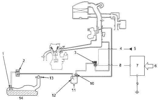
- 1. FUEL TANK EVAP VALVE
- 2. EVAP TWO WAY VALVE
- 3. EVAP PURGE CONTROL SOLENOID VALVE
- 4. BLK/YEL
- 5. IG COIL (15A) FUSE
- 6. VARIOUS SENSORS
- 7. ECM/PCM
- 8. RED
- 9. BLK
- 10. EVAP PURGE CONTROL
DIAPHRAGM VALVE - 11. FRESH AIR
- 12. EVAP CONTROL CANISTER
- 13. FUEL FILL CAP
- 14. FUEL TANK
PDF p. 437 · 11-107
without TWC models:
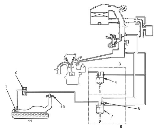
- 1. FUEL TANK EVAP VALVE
- 2. EVAP TWO WAY VALVE
- 3. (without PCV)
- 4. EVAP CONTROL CANISTER
- 5. FRESH AIR
- 6. EVAP PURGE CONTROL DIAPHRAGM VALVE
- 7. EVAP CONTROL CANISTER
- 8. (with PCV)
- 9. FRESH AIR
- 10. FUEL FILL CAP
- 11. FUEL TANK
PDF p. 438 · 11-108
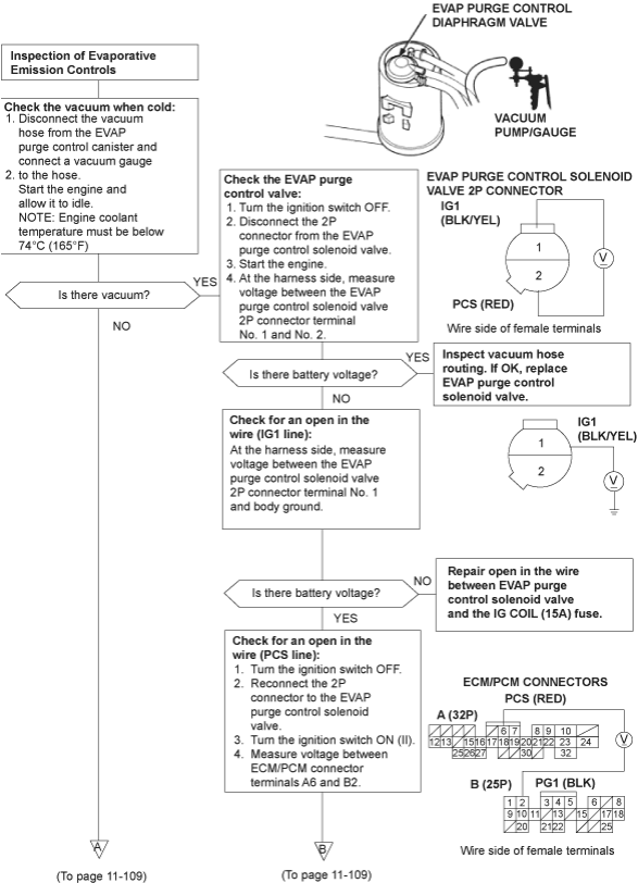
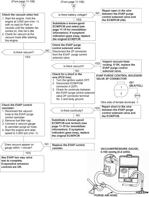
Troubleshooting (with TWC models)
PDF p. 439 · 11-109
PDF p. 440 · 11-110
Testing (without TWC models)
- 1.Remove the fuel fill cap.
- 2.Start the engine and allow to idle.
- 3.Disconnect vacuum hose at the EVAP purge control diaphragm valve (on the EVAP control canister) and connect a vacuum gauge to the hose.
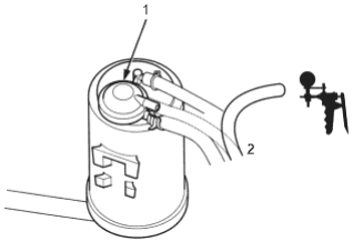
- 1. EVAP PURGE CONTROL DIAPHRAGM VALVE
- 2. VACUUM PUMP/GAUGE
- If there is no vacuum, check vacuum hose for blockage, cracks or disconnected hose, as well as vacuum port for blockage.
- 4.Disconnect the vacuum gauge and reconnect the hose.
- 5.
Connect a vacuum gauge to EVAP control canister purge air hose.
VACUUM/PRESSURE GAUGE, 0-100 mmHg (0.4 in.Hg)
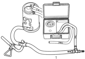
- 1. PURGE AIR HOSE
- 6.
Raise engine speed to 3,500 rpm (min-1).
Vacuum should appear on gauge within 1 minute.
- If vacuum appears on gauge in 1 minute, remove gauge, test is complete.
- If no vacuum, disconnect vacuum gauge and reinstall fuel fill cap.
- 7.Remove EVAP control canister and check for signs of damage or defects.
- If detective, replace EVAP control canister
- 8.
Stop engine. Disconnect upper vacuum hose from EVAP purge control diaphragm valve.
Connect a vacuum pump to lower vacuum as shown, and apply vacuum.
Vacuum should remain steady.
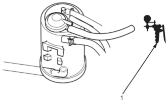
- 1. VACUUM PUMP/GAUGE
- If vacuum drops, replace the EVAP control canister and retest.
- 9.
Restart engine. Reconnect upper vacuum hose to EVAP purge control diaphragm valve.
Vacuum (lower vacuum hose side) should drop to zero.
- If vacuum does not drop to zero, replace the EVAP control canister and retest.
PDF p. 441 · 11-111
Evaporative Emission (EVAP) Two Way Valve Testing
- 1.Remove the fuel fill cap.
- 2.Remove the vapour line from the two way valve on the fuel tank and connect it to a T-fitting from vacuum gauge and vacuum pump as shown
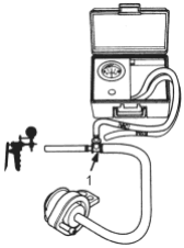
- 1. T-FITTING
- 3.
Apply vacuum slowly and continuously while watching the gauge.
The vacuum should stabilise momentarily at 0.7-2.0 kPa (5-15 mmHg, 0.2-0.6 in.Hg).
If the vacuum stabilises (valve opens) below 0.7 kPa (5 mmHg, 0.2 in.Hg) or above 2.0 kPa (15 mmHg, 0.6 in.Hg), install a new valve and retest.
- 4.Move the vacuum pump hose from the vacuum fitting to the pressure fitting and move the vacuum gauge hose from the vacuum side to pressure side as shown.
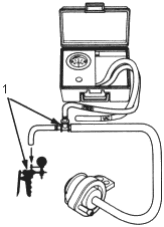
- 1. PRESSURE SIDE
- 5.
Slowly pressurise the vapour line while watching the gauge.
The pressure should stabilise at 1.3-4.7 kPa (10-35 mmHg, 0.4-1.4 in.Hg).
- If the pressure momentarily stabilises (valve opens) at 1.3-4.7 kPa (10-35 mmHg, 0.4-1.4 in.Hg), the valve is OK.
- If the pressure stabilises below 1.3 kPa (10 mmHg, 0.4 in.Hg) or above 4.7 kPa (35 mmHg, 1.4 in.Hg), install a new valve and retest.