PDF p. 431 · 11-101
Description
The throttle body is of a single-barrel side-draft type. The lower portion of the throttle valve is heated by engine coolant from the cylinder head. The idle adjusting screw which increases/decreases bypass air and the Evaporative Emission (EVAP) Control Canister port are located on the top of the throttle body.
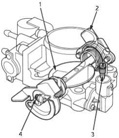
- 1. THROTTLE VALVE
- 2. THROTTLE POSITION (1P) SENSOR
- 3. IDLE ADJUSTING SCREW
- 4. THROTTLE STOP SCREW (Do not adjust.)
Inspection
- 1.Start the engine. Hold the engine at 3,000 rpm (min-1) with no load (in Park or neutral) until the radiator fan comes on, then let it idle.
- 2.Disconnect the vacuum hose (to the EVAP control canister) from the top of the throttle body; connect a vacuum gauge to the throttle body.
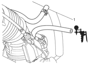
- 1. VACUUM PUMP/GAUGE
- 3.
Allow the engine to idle and check that the gauge indicates no vacuum.
If there is vacuum, check the throttle cable (See Page 11-100).
- 4.
Check that vacuum is indicated on the gauge when the throttle is opened slightly from idle.
If the gauge indicates no vacuum, check the throttle body port. If the throttle body port is clogged, clean it with carburettor cleaner.
- 5.
Stop the engine, and check that the throttle cable operates smoothly without binding or sticking.
If there are any abnormalities in the above steps, check for:
- Excessive wear or play in the throttle valve shaft.
- Sticky or binding throttle link at the fully closed position.
- Clearance between throttle stop screw and throttle lever at the fully closed position
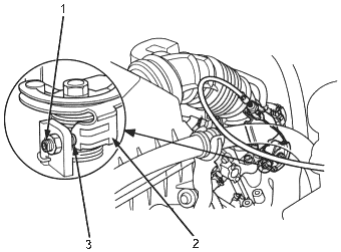
Replace the throttle body if there is excessive play in
the throttle valve shaft or if the shaft is binding or
- 1. THROTTLE STOP SCREW (Do not adjust.)
- 2. THROTTLE LINK
- 3. There should be no clearance.
sticking.
PDF p. 432 · 11-102
Removal
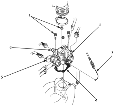
NOTE:
- Do not adjust the throttle stop screw.
- After reassembly, adjust the throttle cable (See Page 11-100).
- The TP sensor is not removable.
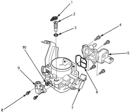
Disassembly
- 1. 22 Nm (2.2 kgf/m, 16 lbf/ft)
- 2. MAP SENSOR
- 3. THROTTLE CABLE
- 4. GASKET, Replace.
- 5. IAC VALVE
- 6. TP SENSOR
- 1.CAP
- 2.IDLE ADJUSTING SCREW
- 3.O-RING
- 4.3.5 Nm (0.35 kgf/m, 2.6 lbf/ft)
- 5.IAC VALVE (See Page 11-63)
- 6.O-RING. Replace
- 7.TP SENSOR (See Page 11-41)
- 8.2.1 Nm (0.21 kgf/m, 1.5 lbf/ft)
- 9.MAP SENSOR (See Page 11-34)
- 10.O-RING, Replace