PDF p. 306 · 8-10
- 1.Drain the engine oil.
- 2.Turn the crankshaft and align the white groove on the crankshaft pulley with the pointer on the lower cover.
- 3.Remove the cylinder head cover and upper cover.
- 4.Remove the power steering pump belt, air conditioner belt and the alternator belt.
- 5.Remove the crankshaft pulley and remove the lower cover
- 6.Remove the timing belt.
- 7.Remove the drive pulley.
- 8.Remove the oil pan and oil screen.
- 9.Remove the oil pump.
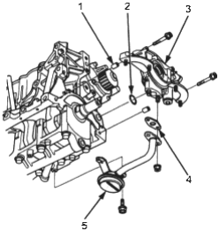
- 1. DOWEL PIN
- 2. O-RING. Replace.
- 3. OIL PUMP
- 4. GASKET. Replace.
- 5. OIL SCREEN
- 10.Remove the screws from the pump housing, then separate the housing and cover.
- 11.
Check the inner-to-outer radial clearance on the pump rotor. If the inner-to-outer rotor clearance exceeds the service limit, replace the inner and outer rotors.
Inner Rotor-to Rotor Radial Clearance
Standard (New): 0.02 - 0.14 mm (0.001 - 0.006 in) Service Limit: 0.20 mm (0.008 in)
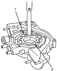
- 1. OUTER ROTOR
- 2. INNER ROTOR
- 12.
Check the housing-to-rotor clearance on the pump rotor. If the housing-to-rotor axial clearance exceeds the service limit, replace the set of inner and outer rotors and/or the pump housing.
Housing-to-Rotor Clearance
Standard (New): 0.03 - 0.08 mm (0.001 - 0.003 in) Service Limit: 0.15 mm (0.006 in)
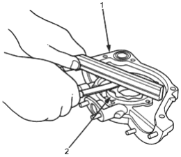
- 1. HOUSING
- 2. ROTORS
PDF p. 307 · 8-11
- 13.
Check the housing-to-outer rotor radial clearance. If the housing-to-outer rotor radial clearance exceeds the service limit, replace the set of inner and outer rotors and/or pump housing.
Housing-to-Outer Rotor Radial Clearance
Standard (New): 0.10 - 0.18 mm (0.004 - 0.007 in) Service Limit: 0.20 mm (0.008 in)
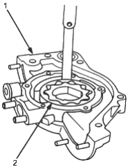
- 1. HOUSING
- 2. OUTER ROTOR
- 14.Inspect both rotors and pump housing for scoring or other damage. Replace parts if necessary.
- 15.Remove the old oil seal from the oil pump.
- 16.
Using the special tool, gently tap in the new oil seal until the driver bottoms against the pump.
NOTE: The oil seal alone can be replaced without removing the oil pump.
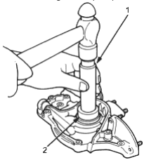
- 1. HANDLE DRIVER, 07749-0010000
- 2. DRIVER ATTACHMENT, 52 x 55 mm, 07746-0010400
- 17.Reassemble the oil pump, applying thread lock to the pump housing screws.
- 18.Check that the oil pump turns freely.
- 19.Apply alight coat of oil to the seal lip.
- 20.Install the two dowel pins and new O-ring on the oil pump.
- 21.
Apply liquid gasket to the cylinder block mating surface of the oil pump.
NOTE:
- Use liquid gasket, part No. 08C70-K0234M, 08C70-K0334M or 08C70-X0331S.
- Check that the mating surfaces are clean and dry before applying liquid gasket.
- Apply liquid gasket evenly, being careful to cover all the mating surface.
- To prevent leakage of oil, apply liquid gasket to the inner threads of the bolt holes.
- Do not install the parts if five minutes or more have elapsed since applying the liquid gasket. Instead, reapply liquid gasket after removing the old residue.
- After assembly, wait at least 30 minutes before filling the engine with oil.
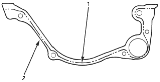
- 1. Apply liquid gasket along the broken line.
- 2. PUMP HOUSING
PDF p. 308 · 8-12
- 22.Install the oil pump on the cylinder block.
- Apply grease to the lip of the pump seal. Then, install the oil pump onto the crankshaft. When the pump is in place, clean any excess grease off the crankshaft and check that the oil seal lip is not distorted.
- 23.Install the oil screen.
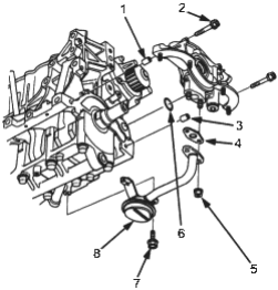
- 1. DOWEL PIN
- 2. 6 x 1.0 mm, 11 Nm (1.1 kgf/m, 8.0 lbf/ft)
- 3. DOWEL PIN
- 4. GASKET. Replace
- 5. 6 x 1.0 mm, 11 Nm (1.1 kgf/m, 8.0 lbf/ft)
- 6. O-RING. Replace
- 7. 6 x 1.0 mm, 11 Nm (1.1 kgf/m, 8.0 lbf/ft)
- 8. OIL SCREEN
- 24.Install the oil pan, (See Page 7-25).