PDF p. 265 · 6-26
NOTE:
- For best results, heat cylinder head to 150°C (300°F) before removing or installing guides.
- It may be necessary to use an air hammer to remove some valve guides.
- 1.Drive the valve guide out from the bottom of the cylinder head.
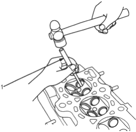
- 1. VALVE GUIDE DRIVER, 5.5 mm, 07742-0010100
- 2.Drive in a new valve guide to the specified depth.
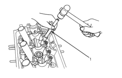
- 1. VALVE GUIDE DRIVER, 5.5 mm, 07742-0010100
Valve Guide Installed Height:
Intake: 17.85 - 18.35 mm (0.703 - 0.722 in) Exhaust: 18.65 - 19.15 mm (0.734 - 0.754 in)
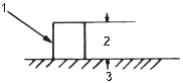
- 1. VALVE GUIDE
- 2. Measure here
- 3. CYLINDER HEAD
Reaming
NOTE: For new valve guides only.
- 1.Coat both the reamer and valve guide with cutting oil.
- 2.Rotate the reamer clockwise the full length of the valve guide bore.
- 3.Continue to rotate the reamer clockwise while removing it from the bore.
- 4.Thoroughly wash the guide in detergent and water to remove any cutting residue.
- 5.Check the clearance with a valve (see page 6-24).
- Verify that the valve slides in the valve guide without exerting pressure.
NOTE: Turn reamer in clockwise direction only
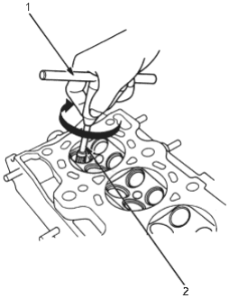
- 1. REAMER HANDLE
- 2. VALVE GUIDE REAMER, 5.525 mm, 07HAH-PJ70100