PDF p. 253 · 6-14
Engine Removal is not required in this procedure.
NOTE:
- Use fender covers to avoid damaging painted surfaces.
- To avoid damage, carefully unplug the wiring connectors while holding the connector portion.
- To avoid damaging the cylinder head, wait until the engine coolant temperature drops below 38°C (100°F) before loosening the retaining bolts.
- Mark all wiring and hoses to avoid misconnection. Also, be sure that they do not contact other wiring or hoses, or interfere with other parts.
- 1.Secure the hood in the open position.
- 2.Disconnect the battery negative terminal first, then the positive terminal.
- 3.Drain the engine coolant (see page 10-5).
- 4.Remove the intake air duct B.
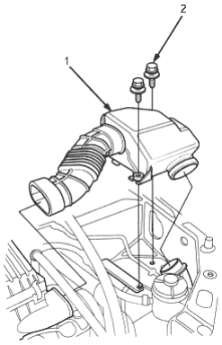
- 1. INTAKE AIR DUCT B
- 2. 6 x 1.0 mm, 9.8 Nm (1.0 kgf/m, 7.2 lbf/ft)
- 5.Remove the breather hose then disconnect the intake air temperature (IAT) sensor connector.
- 6.Remove the air cleaner housing and the intake air duct.
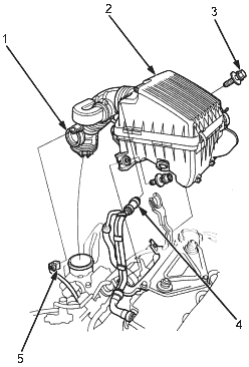
- 1. INTAKE AIR DUCT
- 2. AIR CLEANER HOUSING
- 3. 6 x 1.0 mm, 9.8 Nm (1.0 kgf/m, 7.2 lbf/ft)
- 4. BREATHER HOSE
- 5. IAT SENSOR CONNECTOR
- 7.Remove the mounting bolt and lock bolt, then remove the power steering (P/S) pump belt and pump without disconnecting the P/S hoses.
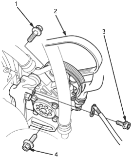
- 1. MOUNTING BOLT, 8 x 1.25 mm, 24 Nm (2.4 kgf/m, 17 lbf/ft)
- 2. P/S PUMP BELT
- 3. 6 x 1.0 mm, 9.8 Nm (1.0 kgf/m, 7.2 lbf/ft)
- 4. LOCK BOLT, 8 x 1.25 mm, 24 Nm (2.4 kgf/m, 17 lbf/ft)
PDF p. 254 · 6-15
- 8.Remove the P/S pump bracket.
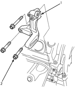
- 1. P/S PUMP BRACKET
- 2. 10 x 1.25 mm, 44 Nm (4.5 kgf/m, 33 lbf/ft)
- 9.Loosen the idler pulley centre nut and adjusting bolt, then remove the air conditioning (A/C) compressor belt.
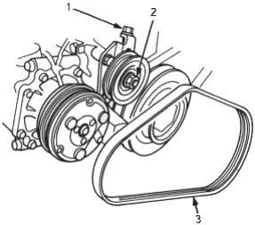
- 1. ADJUSTING BOLT
- 2. IDLER PULLEY CENTRE NUT, 10 x 1.25 mm, 44 Nm (4.5 kgf/m, 33 lbf/ft)
- 3. A/C COMPRESSOR BELT
- 10.Loosen the mounting nut and lock bolt, then remove the alternator belt.
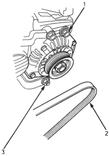
- 1. LOCK BOLT, 8 x 1.25 mm, 24 Nm (2.4 kgf/m, 17 lbf/ft)
- 2. ALTERNATOR BELT
- 3. MOUNTING NUT, 10 x 1.25 mm, 44 Nm (4.5 kgf/m, 33 lbf/ft)
- 11.Remove the engine mount bracket A and alternator upper bracket.
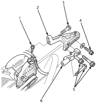
- 1. 6 x 1.0 mm, 9.8 Nm (1.0 kgf/m, 7.2 lbf/ft)
- 2. ALTERNATOR UPPER BRACKET
- 3. 10 x 1.25 mm, 44 Nm (4.5 kgf/m, 33 lbf/ft)
- 4. LOCK BOLT, 8 x 1.25 mm, 24 Nm (2.4 kgf/m, 17 lbf/ft)
- 5. 10 x 1.25 mm, 44 Nm (4.5 kgf/m, 33 lbf/ft)
- 6. ENGINE MOUNT BRACKET A
PDF p. 255 · 6-16
- 12.
Remove the throttle cable by loosen the locknut, then slip the cable end out of the accelerator linkage.
NOTE:
- Take care not to bend the cable when removing it. Always replace any kinked cable with a new one.
- Adjust the throttle cable when installing (see section 11).
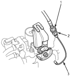
- 1. LOCKNUT
- 2. ADJUSTING NUT
- 3. THROTTLE CABLE
- 13.Relieve fuel pressure (see section 11).
- 14.Remove the fuel feed hose, fuel return hose and evaporative emission (EVAP) control canister hose.
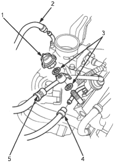
- 1. 33 Nm (3.4 kgf/m, 25 lbf/ft)
- 2. EVAP CONTROL CANISTER HOSE
- 3. WASHERS, Replace.
- 4. FUEL RETURN HOSE
- 5. FUEL FEED HOSE
- 15.Remove the brake booster vacuum hose, positive crankcase ventilation (PCV) hose and vacuum hose..
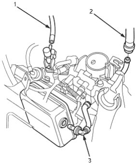
- 1. VACUUM HOSE
- 2. BRAKE BOOSTER VACUUM HOSE
- 3. PCV HOSE
- 16.Remove the upper radiator hose, heater hose and water bypass hoses.
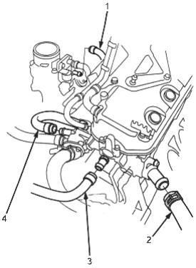
- 1. WATER BYPASS HOSE
- 2. RADIATOR UPPER HOSE
- 3. HEATER HOSE
- 4. WATER BYPASS HOSE
PDF p. 256 · 6-17
- 17.Remove the engine wire harness connectors and wire harness clamps from the cylinder head and the intake manifold.
- Four injector connectors
- Idler air control (IAC) valve connector
- Throttle position sensor connector
- Manifold absolute pressure (MAP) sensor connector
- Engine coolant temperature (ECT) sensor connector
- Radiator fan switch connector
- Coolant temperature gauge sending unit connector
- Heated oxygen sensor (HO2S) connector
- 18.Remove the spark plug caps and distributor from the cylinder head.
- 19.Support the engine with the jack and wood block under the oil pan.
- 20.Remove the side engine mount.
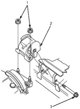
- 1. 12 x 1.25 mm, 74 Nm (7.5 kgf/m, 54 lbf/ft)
- 2. SIDE ENGINE MOUNT
- 3. 12 x 1.25 mm, 74 Nm (7.5 kgf/m, 54 lbf/ft)
- 21.Remove air cleaner housing bracket, then remove the cylinder head cover
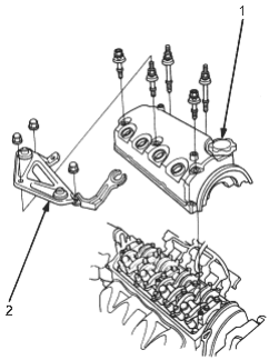
- 1. CYLINDER HEAD COVER
- 2. AIR CLEANER HOUSING BRACKET
- 22.Remove the timing belt (see page 6-8).
- 23.Remove camshaft pulley and back cover.
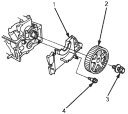
- 1. BACK COVER
- 2. CAMSHAFT PULLEY. Clean when installing.
- 3. 8 x 1.25 mm, 37 Nm (3.8 kgf/m, 27 lbf/ft). Apply engine oil to the bolt threads.
- 4. 6 x 1.0 mm, 12 Nm (1.2 kgf/m, 8.7 lbf/ft)
PDF p. 257 · 6-18
- 24.Remove the exhaust manifold (see page 9-3).
- 25.Remove the intake manifold (see page 9-2).
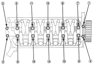
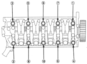
- 26.Remove the cylinder head bolts. To prevent warpage, unscrew the bolts in sequence 1/3 turn at a time; repeat the sequence until all bolts are loosened.
CYLINDER HEAD BOLT LOOSING SEQUENCE:
- 27.Remove the cylinder head.
Rocker Arms
Removal
- 1.Loosen the adjusting screws.
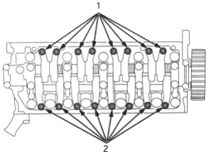
- 1. ADJUSTING SCREWS
- 2. ADJUSTING SCREWS
- 2.
Unscrew the camshaft holder bolts, then remove the rocker arm assembly.
NOTE:
- Unscrew the camshaft holder bolts two turns at a time, in a criss-cross pattern, to prevent damaging the valves or rocker arm assembly.
- When removing the rocker arm assembly, do not remove the camshaft holder bolts. The bolts will keep the camshaft holders, the springs and the rocker arms on the shaft.
CAMSHAFT HOLDER BOLTS LOOSENING SEQUENCE: