PDF p. 214 · 4-30
- 1.Disconnect the battery negative terminal first, then the positive terminal.
- 2.Remove the harness stay from the upper bracket.
- 3.Disconnect the 4P (or 3P) connector and B terminal wire from the alternator.
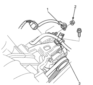
- 1. B TERMINAL WIRE
- 2. TERMINAL NUT, 8 Nm (0.8 kgf/m, 6 lbf/ft)
- 3. HARNESS STAY
- 4.Remove the adjusting bolt, mounting nut and mounting bolts, then remove the alternator bracket and engine mount bracket A.
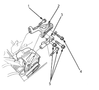
- 1. 10 x 1.25 mm, 44 Nm (4.5 kgf/m, 33 lbf/ft)
- 2. ALTERNATOR BRACKET
- 3. ENGINE MOUNT BRACKET A
- 4. 8 x 1.25 mm, 24 Nm (2.4 kgf/m, 17 lbf/ft)
- 5. 10 x 1.25 mm, 44 Nm (4.5 kgf/m, 33 lbf/ft)
- 5.Pull out the through bolt, then remove the alternator belt and alternator.
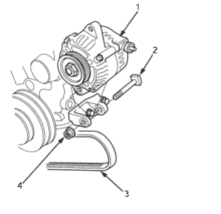
- 1. ALTERNATOR
- 2. THROUGH BOLT MOUNTING NUT
- 3. ALTERNATOR BELT
- 4. LOCKNUT, 10 x 1.25 mm, 44 Nm (4.5 kgf/m, 33 lbf/ft)
- 6.Install the alternator in reverse order of removal.
- 7.Adjust the alternator belt tension (See Page 4-40).