PDF p. 1235 · 23-F-16
- 1.Remove the driver’s lower pocket (see section 20).
- 2.Disconnect the 4P [3P] connector from the cable reel.
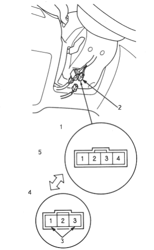
- 1. CVT
- 2. 4P [3P] CONNECTOR
- 3. Not used
- 4. M/T
- 5. Wire side of female terminals
[ ]: M/T
- 3.Check for continuity between the cable reel No. 4 [2] terminal and body ground in each switch position.
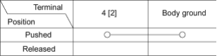
[ ]: M/T
- If there is continuity, the horn switch is OK.
- If there is no continuity, go to step 4.
- 4.Remove the SRS airbag assembly (see section 24)
- 5.Check for continuity between the cable reel No. 4 [2] terminal and horn switch positive terminal.
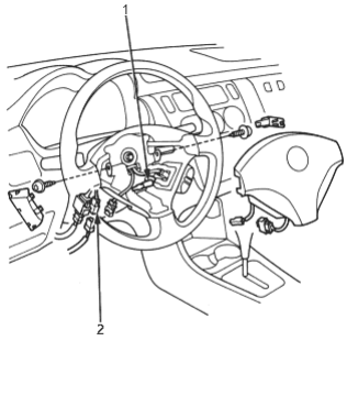
- 1. HORN SWITCH POSITIVE TERMINAL
- 2. CABLE REEL 4P [3P] CONNECTOR
[ ]: M/T
- If there is continuity, replace the horn switch (SRS airbag assembly, see section 24).
- If there is no continuity, replace the cable reel (see section 24) and confirm the proper operation.