PDF p. 1231 · 23-F-12
- 1.Remove the power mirror from the door (see section 20) and disconnect the 6P or 3P connector.
- 2.Cut the wire harness with wire cutter.
- 3.Remove the seat base.
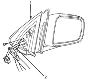
- 1. SEAT BASE
- 2. WIRE HARNESS
- 4.Remove the mounting screws and separate the mirror base from the mirror housing.
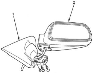
- 1. MIRROR BASE
- 2. MIRROR HOUSING
- 5.Insert a flat tip screwdriver into the two slots. The mirror is fastened to the actuator with double sided adhesive tape. Twist the screwdriver gently to release the mirror. (Protect the paint with a towel inserted between the screwdriver and the mirror housing.)
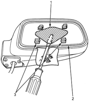
- 1. ADHESIVE TAPE
- 2. MIRROR HOLDER
- 3. LOCATOR CLIPS
- 6.Remove the screws and the actuator from the housing.
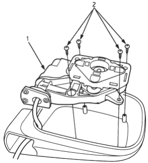
- 1. ACTUATOR
- 2. SCREWS
PDF p. 1232 · 23-F-13
- 7.Install in the reverse order of removal. Replace the seat base and three screws with new ones.
- 8.Insert the terminals into the connector in the original arrangement as shown below.
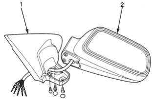
- 1. MIRROR BASE
- 2. MIRROR HOUSING
With mirror defogger:
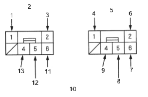
- 1. BLU/RED
- 2. LEFT
- 3. BLK/WHT
- 4. BLU/RED
- 5. RIGHT
- 6. BLK/WHT
- 7. BLU/BLK
- 8. BLU/GRN
- 9. YEL/WHT
- 10. Wire side of female terminals
- 11. YEL/BLK
- 12. YEL/RED
- 13. YEL/WHT
With retractable power mirror:
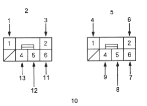
- 1. BLK
- 2. LEFT
- 3. WHT
- 4. WHT
- 5. RIGHT
- 6. BLK
- 7. BLU/BLK
- 8. BLU/GRN
- 9. YEL/WHT
- 10. Wire side of female terminals
- 11. YEL/BLK
- 12. YEL/RED
- 13. YEL/WHT
Without mirror defogger and retractable power mirror
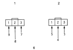
- 1. LEFT
- 2. RIGHT
- 3. BLU/BLK
- 4. BLU/GRN
- 5. YEL/WHT
- 6. Wire side of female terminals
- 7. YEL/BLK
- 8. YEL/RED
- 9. YEL/WHT