PDF p. 1228 · 23-F-9
- 1.Remove the driver’s door panel (see section 20).
- 2.Disconnect the 10P connector from the power mirror switch.
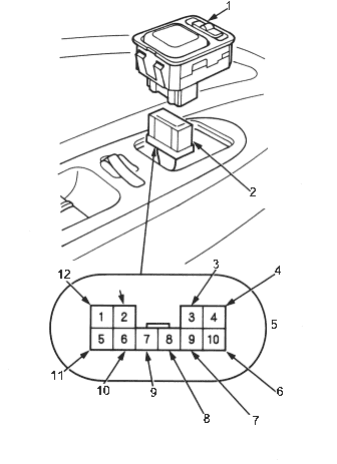
- 1. POWER MIRROR SWITCH
- 2. 10P CONNECTOR
- 3. BLK/YEL
- 4. YEL/RED
- 5. Wire side of female connectors
- 6. BLU/BLK [YEL/BLK]
- 7. YEL/BLK [BLU/BLK]
- 8. LT BLU [GRN/WHT]
- 9. GRN/WHT [LT BLU]
- 10. *1 BLU/YEL, *2 GRN/ORN
- 11. GRN/YEL
- 12. BLK/YEL
- 13. BLK
[ ]: RHD type
- *1:With defogger
- *2:With retractable power mirror
Mirror Test
Both Inoperative:
- 1.
Check for voltage between the No. 1 terminal and body ground with the ignition switch ON (II).
There should be battery voltage.
- If there is no battery voltage, check for:
- Blown No. 11 (7.5A) fuse in the under-dash fuse/relay box.
- An open in the BLK/YEL wire.
- If there is battery voltage, go to step 2.
- If there is no battery voltage, check for:
- 2.
Check for continuity between the No. 2 terminal and body ground.
There should be continuity.
- If there is no continuity, check for:
- An open in the BLK wire.
- If there is no continuity, check for:
Left mirror inoperative:
Connect the No. 1 terminal to the No. 7 terminal and the No. 4 (or No. 9) terminal to body ground with jumper wires. The left mirror should tilt down (or swing left) with the ignition switch ON (II).
- If the mirror does not tilt down (or does not swing left) check for an open in the No. 4 (or No. 9) terminal wire between the left mirror and the 10P connector. If the wire is OK, check the left mirror actuator.
- If the mirror neither tilts down nor swings left, repair the No. 7 terminal wire.
- If the mirror works properly, check the mirror switch.
Right mirror inoperative:
Connect the No. 1 terminal to the No. 8 terminal and the No. 4 (or No. 10) terminal to body ground with jumper wires. The right mirror should tilt down (or swing left) with the ignition switch ON (II).
- If the mirror does not tilt down (or does not swing left) check for an open in the No. 4 (or No. 10) terminal wire between the left mirror and the 10P connector. If the wire is OK, check the left mirror actuator.
- If the mirror neither tilts down nor swings left, repair the No. 8 terminal wire.
- If the mirror works properly, check the mirror switch.
Defogger Test:
Connect the No. 3 and No. 6 terminals with a jumper wire and check for voltage between the No. 3 terminal and body ground.. There should be battery voltage and both mirrors should warm up with the ignition switch ON (II).
- If there is no voltage or neither warms up, check for:
- An open in the BLK/YEL and BLU/YEL wires.
- Blown No. 11 (7.5A) in the under-dash fuse/relay box.
- Poor ground (G401, G402).
- If only one fails to warm up, check its defogger.
- If both fail to warm up, check the defogger switch. Retractable Mirror Inoperative:
Connect the No. 1 (BLK/YEL) terminal of the 10P connector to the No. 6 (GRN/ORN) terminal and the No. 5 (GRN/YEL) terminal to body ground with jumper wires. The mirrors should extend when the ignition switch is turned ON (II).
Connect the No. 1 (BLK/YEL) terminal of the 10P connector to the No. 5 (GRN/YEL) terminal and the No. 6 (GRN/ORN) terminal to body ground with jumper wires. The mirrors should retract when the ignition switch is turned ON (II).
- If one of the mirrors does not retract or extend, check the retractable mirror actuator.
- If the mirrors operate properly, replace the switch.
- Poor ground (G401, G402).
- If there is continuity, check both mirrors individually as described in the next column.