PDF p. 1166 · 23-C-14
NOTE: Before testing, check the No. 6 (7.5A) fuse in the under-dash fuse/relay box.
- 1.Carefully remove the dashboard lower cover.
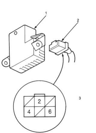
- 1. VEHICLE SPEED ALARM UNIT
- 2. 6P CONNECTOR
- 3. Wire side of female terminals
- 2.
Check for continuity between the No. 6 terminal and the body ground.
There should be continuity.
- If there is no continuity, check for:
- An open in the BLK wire
- Poor ground (G401, G402).
- If there is continuity, go to step 3.
- If there is no continuity, check for:
- 3.
Check for voltage between the No. 4 terminal and the body ground with the ignition switch ON (II).
There should be battery voltage.
- If there is no voltage, check for an open in the YEL wire.
- If there is battery voltage, go to step 4.
- 4.Ignition switch OFF, reconnect the 6P connector to the speed alarm unit and connect the voltmeter to the No. 2 wire terminal.
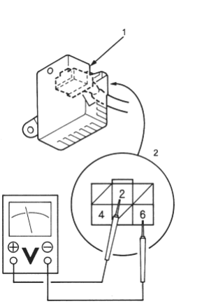
- 1. VEHICLE SPEED ALARM UNIT
- 2. Wire side of female terminals
- 5.Raise the car and place safety stands in the proper locations (see section 1).
- 6.Turn the ignition switch ON (II) again and rotate the front wheel slowly, then check to see the voltmeter moves from 0V to about 5V or more and then from about 5V or more to 0V alternatively.
- If there is no voltage, check for:
- Vehicle speed sensor (VSS) (See Page 23-C-11).
- An open in the BLU/WHT wire.
- If there is no voltage, check for:
- 7.Replace the speed alarm unit if the vehicle speed sensor (VSS) circuit is normal.