PDF p. 1060 · 22-5
The air conditioner system removes heat from the passenger compartment by circulating refrigerant through the systems as shown below.
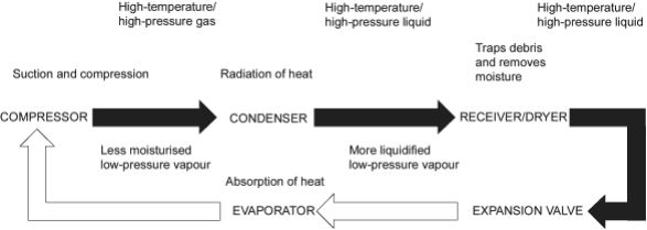
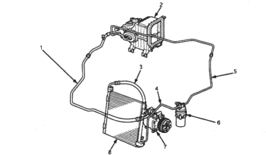
- 1. SUCTION LINE (LOW-PRESSURE SIDE)
- 2. EVAPORATOR
- 3. DISCHARGE LINE (HIGH-PRESSURE SIDE)
- 4. CONDENSER LINE
- 5. LIQUID LINE
- 6. RECEIVER/DRYER
- 7. COMPRESSOR
- 8. CONDENSER
This vehicle uses HFC-134a (R-134a) refrigerant which does not contain chlorofluorocarbons. Pay attention to the following service items:
- Do not mix refrigerants CFC-12 (R-12) and HFC-134a (R-134a). They are not compatible.
- Use only the recommended polyalkyleneglycol (PAG) refrigerant oil (KEIHIN, SP1-) designed for the R-134a compressor. Intermixing the recommended (PAG) refrigerant oil with any other refrigerant oil will result in compressor failure.
- All A/C system parts (compressor, discharge line, suction line, evaporator, condenser, receiver/dryer, expansion valve, O-rings for joints) have to be proper for refrigerant R-134a. Do not confuse with R-12 parts.
- Use a halogen gas leak detector designed for refrigerant R-134a.
- Use a vacuum pump adapter which is equipped with a check valve to prevent backflow of the vacuum pump oil.
- Separate the manifold gauge sets (pressure gauges, hoses, joints) for refrigerants R-12 and R-134a. Do not confuse them.