PDF p. 1624 · 4-15
- 1.Remove the related parts.
- Front suspension parts.
- Brake hose and lines.
- Engine compartment electrical components.
- Fittings in passenger compartment, etc.
- Steering gearbox.
- 2.Remove the rear beam.
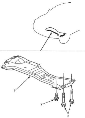
- 1. REAR BEAM
- 2. 12 x 1.25 mm, 64 Nm (6.5 kgf/m, 47 lbf/ft)
- 3. SPECIAL BOLTS, 12 x 1.25 mm, 64 Nm (6.5 kgf/m, 47 lbf/ft)
- 3.Roughly pull out and straighten the damaged area.
- Attach the vehicle to the frame straightener by tightening the underbody clamps located at the horizontal pinch welds.
NOTE: Refer to the HR-V Shop Manual for safety stand location points.
- Before cutting off the damaged sections, pull them out so that they are restored to the original shape.
- Cutting off the front side frame before pulling out the damage makes repair of the front floor, dashboard lower and other related parts difficult.
- 4.Peel off the undercoat. Heat the undercoat at the weld areas of the lower dashboard, front floor and side sill with a gas torch and peel off the undercoat with a metal spatula.
- 5.
Remove the front side frame.
NOTE: It is not necessary to separate the front wheelhouse from the front side frame if the wheelhouse/damper housing also needs replacing.
- Centre punch around the spot weld imprints on the wheelhouse, damper housing, lower arm support, dashboard lower and lower arm support.
- Using a spot cutter, drill holes in the spot welded areas.
- Peel off the welding flange using a chisel.
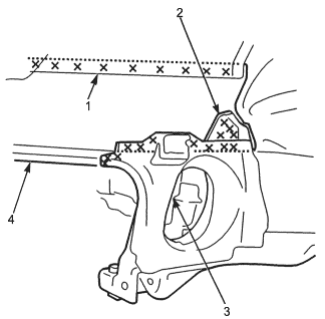
- 1. DAMPER HOUSING
- 2. OUTRIGGER GUSSET
- 3. LOWER ARM SUPPORT
- 4. FRONT SIDE FRAME
PDF p. 1625 · 4-16
- Centre punch around the spot weld imprints on the front side frame from inside the passenger compartment.
- Drill holes in the spot welded area with a 5 mm (0.2 in.) drill.
NOTE: Drill holes completely through the parts since the replacement front side frame will be welded by MIG welding.
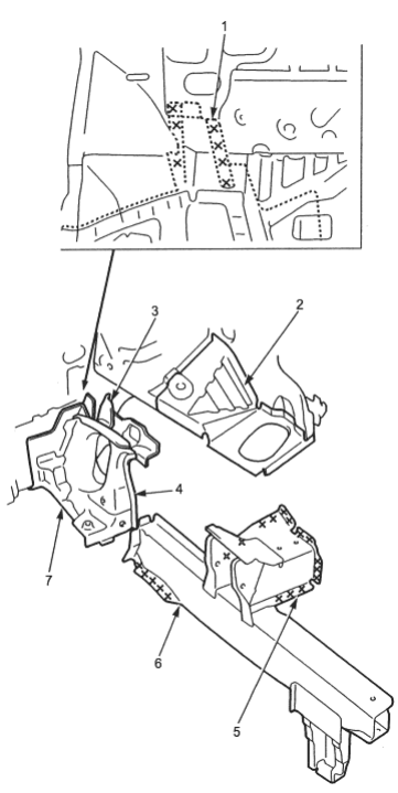
- 1. FRONT SIDE FRAME
- 2. FRONT WHEELHOUSE
- 3. OUTRIGGER GUSSET
- 4. LOWER ARM SUPPORT
- 5. ENGINE MOUNT BRACKET SUPPORT
- 6. FRONT SIDE FRAME
- 7. FRONT SIDE OUTRIGGER
- 6.
Check the front side outrigger and lower arm support for position and damage.
If necessary, replace the front side out rigger and lower arm support as an assembly.
- Leave the inside sill extension attached to the dashboard lower side.
- Centre punch around the spot weld imprints on the outer panel, floor frame and inside sill.
- Drill holes in the centre punched areas using a spot weld cutter.
NOTE: When drilling holes be careful not to drill down to the floor frame and the inside sill.
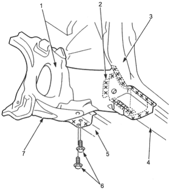
- 1. LOWER ARM SUPPORT
- 2. INSIDE SILL EXTENSION
- 3. OUTER PANEL
- 4. INSIDE SILL
- 5. FLOOR FRAME
- 6. MOUNTING BOLTS 6 x 1.0 mm
- 7. FRONT SIDE OUTRIGGER
PDF p. 1626 · 4-17
- Centre punch around the spot weld imprints on the front side outrigger from inside the passenger compartment.
- Drill holes in the centre punched areas with a 5 mm (0.2 in) spot weld cutter.
NOTE: Drill holes through the parts completely since the replacement front side outrigger will be welded by MIG welding.
- Remove the MIG welds of the front side outrigger and dashboard lower cross-member with a disc sander.
- Drill holes to the spot welds of A portions with a spot weld cutter from under the front floor.
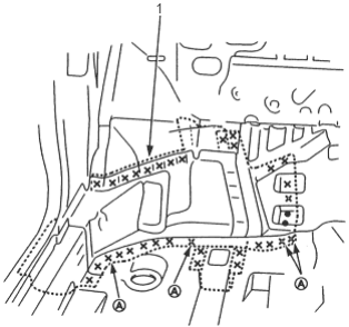
- 1. FRONT SIDE OUTRIGGER
- Level off and finish the burrs of the pried off spot welds with a disc sander.
- 7.
Straighten the related parts.
Reshape the dashboard lower, floor frame, front floor, inside sill and side sill inner joint using a hammer and dolly. Check the floor frame and inside sill for position and damage.
- 8.Set the new front side outrigger and front side frame.
- Remove the undercoat from both sides of the welding section and expose the steel plate using a disc sander.
NOTE: Apply the spot sealer to the welding surface when spot welding.
- Tighten the front side frame against the front floor and side sill using vice-grips or pliers.
- Drill 3 mm (0.12 in.) holes and screw 5 mm self-tapping screws into the drilled holes at the areas where the front side outriggers do not fit closely.
- Even out the welded flange and damaged area with a hammer and dolly.
- Place a jack under the front side outrigger and support it, then measure the positions for temporary attachment.
NOTE: Use of a positioning jig is recommended (see page 1-7).
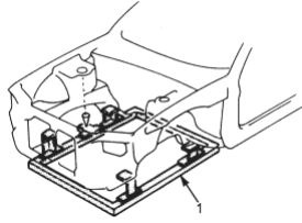
- 1. POSITIONING JIG
- Clamp the front bulkhead and front wheelhouse/damper housing with squill vices and vice-grips.
- Measure the front compartment diagonally.
- Spot weld several points in the clamped sections and temporarily attach the front side frame and front side outrigger.
- Check the body dimensions (see section 6).
- Install the rear beam and check the front side frame position.
PDF p. 1627 · 4-18
- 9.Perform the main welding.
- Make 20% to 30% more spot welds than there were holes drilled.
NOTE: If there is no room for spot welds, compensate by using MIG welds.
- Weld as much as possible with the jig still mounted.
- Weld the outer panel and front side outrigger.
- Make 5 mm (0.2 in) holes in the MIG weld holes with the front side outrigger and plug weld the floor frame, inside sill and inside sill extension with a MIG welder.
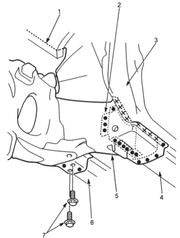
- 1. FRONT SIDE FRAME
- 2. INSIDE SILL EXTENSION
- 3. OUTER PANEL
- 4. INSIDE SILL
- 5. FRONT SIDE OUTRIGGER
- 6. FLOOR FRAME
- 7. MOUNTING BOLTS
- From the passenger compartment side, plug weld the holed areas of the dashboard lower and front floor with a MIG welder.
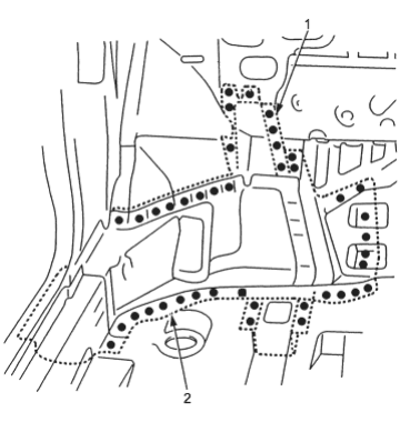
- 1. FRONT SIDE FRAME
- 2. FRONT SIDE OUTRIGGER
- Make 5 mm (0.2 in) holes in the MIG weld holes with the lower arm support and plug weld the front side frame, damper housing and outrigger gusset with a MIG welder.
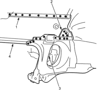
- 1. DAMPER HOUSING
- 2. OUTRIGGER GUSSET
- 3. LOWER ARM SUPPORT
- 4. FRONT SIDE FRAME
PDF p. 1628 · 4-19
- Weld the lower arm support, front side frame, engine mount bracket support and front wheelhouse.
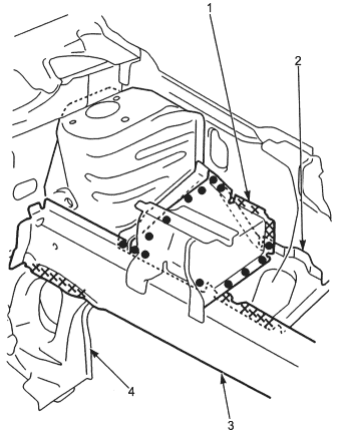
- 1. ENGINE MOUNT BRACKET SUPPORT
- 2. FRONT WHEELHOUSE
- 3. FRONT SIDE FRAME
- 4. LOWER ARM SUPPORT
- 10.Finish the welds. Use a hammer and dolly to even out the damper housing, wheelhouse, dashboard lower, front bulkhead and side sill flanges for a close fit with the surface of the front side frame.
- 11.Apply sealer (see section 5) to the mating surfaces of the lower dashboard, etc.
- 12.Apply the paint. See Paint Repair section.
- 13.
Apply the undercoat.
Undercoat the front floor, and apply anti-rust agent to the inside of the welding section of the side sill, front side frame and front side outrigger (see section 7).
- 14.Install the related parts in the reverse order in which they were removed.
- 15.Inspect, check and adjust.
- Measure the front wheel alignment.
- Inspect the brake system.
- Adjust the headlight aim.