PDF p. 1594 · 1-4
Connect the frame corrector to the vehicle body. The side sill is flangeless to allow reshaping by pulling it out. Use the horizontal pinch welds for anchoring the vehicle.
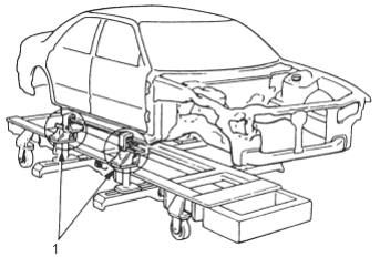
Underbody Clamp:
V.L CHURCHILL Ltd.
PO Box 3, London Road, Daventry, Northants,
NN114NF
TEL + 44 (01327) 704461
FAX + 44 (01327) 71625
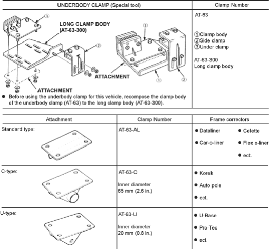
Underbody Clamp Specifications:
- 1.UNDERBODY CLAMPS
PDF p. 1595 · 1-5
- 1.Apply load to the damaged section and pull on it until the section is almost restored to its original shape.
- 2.
Check that the parts of the body are more or less restored to their original shapes.
NOTE: Check the original position using the body dimensional drawings (see section 6) and the positioning jigs (see page 1-7).
- 3.Remove the parts that require replacement.
- 4.Decide whether to replace all the affected parts or to cut the weld joint parts and replace them.
- 5.
Cut off and separate the damaged parts.
NOTE: When cutting the parts off, take special care that you do not damage adjacent parts on the vehicle.
Setting Conditions for Replacement Parts Joint Sections:
- Make sure that you can perform straightening work after welding.
- Make sure that the locations will not be susceptible to distortion caused by other parts.
- Make sure that there are few removable parts and that the location allows for safe welding.
- Make sure that the joints are short and that the paint repair can be performed easily.
- Make sure the locations are such that the joints can be finished in a way that will not affect the outward appearance.
Make sure that the locations do not hinder the removing and attaching of parts.
NOTE: Keep all of these conditions in mind, and after determining the joint locations, cut the joints for an overlap of 20~30 mm (0.8~1.2 in).
- 6.Straighten the related parts.
- 7.
Set and tack weld the replacement parts.
NOTE: Temporarily mount the related parts and check for clearance and level differences.
- 8.
Weld the replacement parts.
Use proper welding methods (see section 2).
NOTE: Use of the positioning jig is recommended.
The paint film designed to prevent corrosion will be destroyed around the edges of areas that were welded. Therefore these areas and other areas not clearly visible must be repainted. Refer to rust prevention in section 7 of this manual.