PDF p. 908 · 19-B-4
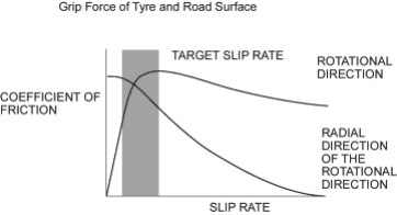
When the brake pedal is depressed during driving, the wheels can lock before the vehicle comes to a stop. In such an event, the manoeuvrability of the vehicle is reduced if the front wheels are locked, and the stability of the vehicle is reduced if the rear wheels are locked, creating an extremely unstable condition. The ABS precisely controls the slip rate of the wheels to ensure maximum grip force from the tyres, and it thereby ensures manoeuvrability and stability of the vehicle.
The ABS calculates the slip rate of the wheels based on the vehicle speed and the wheel speed, then it controls the brake fluid pressure to attain the target slip rate.
PDF p. 909 · 19-B-5
ABS Control
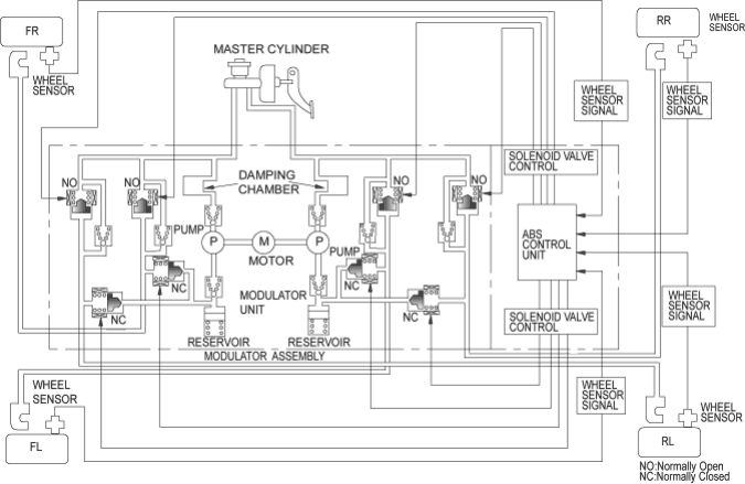
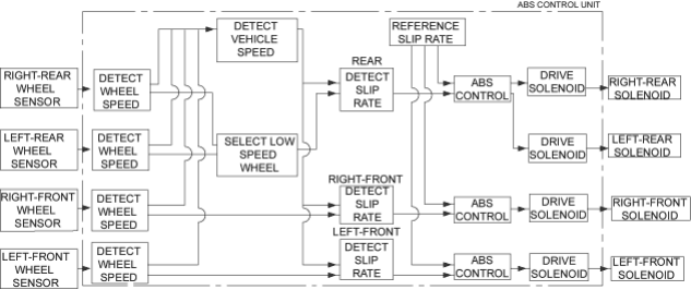
The ABS control unit detects the wheel speed based on the wheel sensor signal it received, then it calculates the vehicle speed based on the detected wheel speed. The control unit detects the vehicle speed during deceleration based on the rate of deceleration.
The ABS control unit calculates the slip rate of each wheel, and it transmits the control signal to the modulator unit solenoid valve when the slip rate is high.
The pressure reduction control has three modes: pressure reduction, pressure retaining, and pressure intensifying modes.
Self-diagnosis Function
The ABS control unit is equipped with a main CPU and a sub CPU, that check each other for problems.
The CPUs checks the circuit of the system.
The ABS control unit turns the ABS and/or brake system indicator when the unit detects a problem, and the unit stops the system.
The self-diagnosis can be classified into these four categories:
- 1.Initial diagnosis
- 2.Except ABS control
- 3.During ABS control
- 4.During warning.
On-board Diagnosis Function
The ABS system can be diagnosed with the Honda PGM Tester.
The ALB Checker cannot be used with this system. For air bleeding, and checking wheel sensor signals, use the Honda PGM Tester. See the Honda PGM Tester user’s manuals for specific operating instructions.
PDF p. 910 · 19-B-6
ABS Modulator
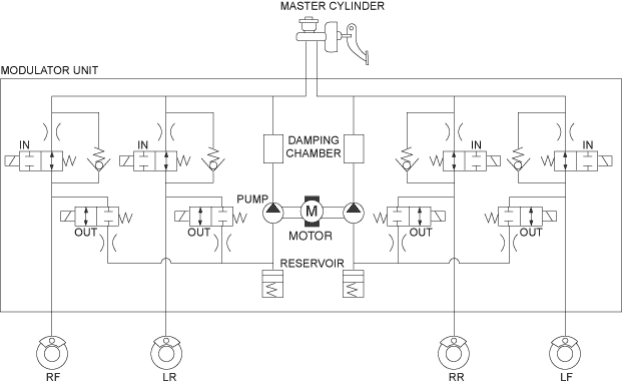
The ABS modulator consists of the inlet solenoid valve, outlet solenoid valve, reservoir, pump, pump motor and the damping chamber.
The modulator reduces the caliper fluid pressure directly. It is a circulating-type modulator because the brake fluid circulates through the caliper, reservoir and the master cylinder. The hydraulic control has three modes: pressure intensifying, pressure retaining and pressure reducing modes.
The hydraulic circuit is an independent four channel-type, one channel for each wheel.
- 1. SOLENOID VALVE
- 2. PUMP MOTOR
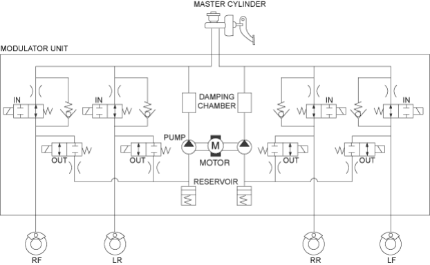
Pressure intensifying mode:
Pressure retaining mode:
Pressure reducing mode:
Motor operation mode:
Inlet valve open, outlet valve closed
Master cylinder fluid is pumped out to the CALIPER.
Inlet valve closed, outlet valve closed
caliper fluid is retained by the inlet valve and outlet valve.
Inlet valve closed, outlet valve open
caliper fluid flows through the outlet valve to the reservoir.
When starting the pressure reducing mode, the pump motor is ON.
When stopping ABS operation, the pump motor is OFF.
The reservoir fluid is pumped out by the pump, through the damping chamber, to the master cylinder.
PDF p. 911 · 19-B-7
Wheel Sensor
The wheel sensors are the magnetic contactless type. As the gear pulsar teeth rotate past the wheel sensor’s magnetic coil, AC current is generated. The AC frequency changes in accordance with the wheel speed. The ABS control unit detects the wheel sensor signal frequency and thereby detects the wheel speed.

Wheel Speed and Modulator Control
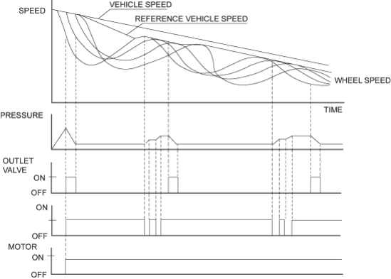
When the wheel speed drops sharply below the vehicle speed, the outlet valve opens momentarily to reduce the caliper fluid pressure. The pump motor starts at this time. As the wheel speed is restored, the inlet valve opens momentarily to increase the caliper fluid pressure.
PDF p. 912 · 19-B-8
Electronic Brake Distribution (EBD)
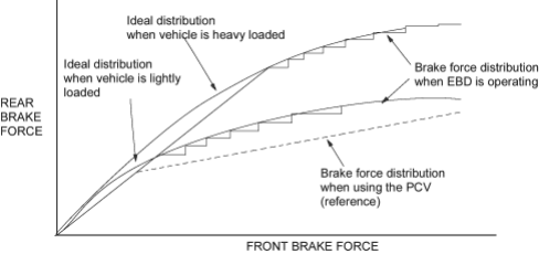
The ABS control unit controls the front and rear brake force distribution suitably according to load movement by changing of carrying condition or deceleration to use the brake force when braking.
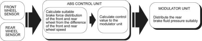
The ABS control unit calculates suitable brake force distribution of the font and rear wheel from the difference of the front and rear wheel speed, and the unit transmits the control signal to the modulator unit. The modulator unit controls the rear brake force suitably.
PDF p. 913 · 19-B-9
EBD Control
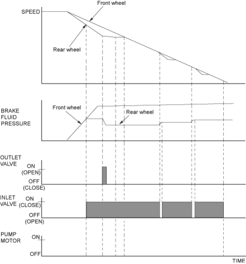
If braking with deceleration more than a certain value, the inlet valve closes to retaining the brake fluid pressure when the rear wheel speed drops below the front wheel speed. When the rear wheel speed drops further, the outlet valve opens momentarily to reduce the brake fluid pressure. As the wheel speed is restored, the inlet valve opens momentarily to increase the brake fluid pressure.
The pump motor does not operate during these operations.