PDF p. 731 · 14-173
- 1.Check that the index mark on the shift lever aligns with the N index mark on the shift indicator panel when the transmission is in N position.
- 2.If the marks do not align, remove the front console (see section 20).
- 3.
Loosen the shift indicator panel mounting screws and adjust by moving the panel.
NOTE: Whenever the shift indicator panel is remove, reinstall the panel as described above.
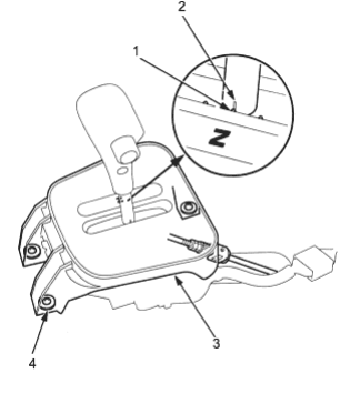
- 1. N INDEX MARK
- 2. INDEX MARK
- 3. SHIFT INDICATOR PANEL
- 4. SCREWS 3 Nm (0.3 kgf/m, 2 lbf/ft)
NOTE: LHD model is shown; RHD is similar
ATF Cooler Hoses
Installation
- 1.Apply transmission fluid to the junction between the ATF cooler line and ATF cooler hose inner.
- 2.
Connect the ATF cooler hoses to the ATF cooler lines and secure them with clips as shown.
NOTE: Be sure to install the clip tabs out of the way of the other parts.
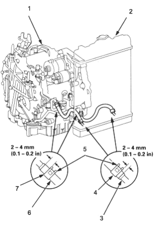
- 1. TRANSMISSION
- 2. RADIATOR
- 3. ATF COOLER LINE
- 4. CLIP
- 5. TAB
- 6. ATF COOLER HOSE
- 7. CLIP