PDF p. 530 · 13-56
NOTE:
- While reassembling the transfer assembly:
- Check and adjust the transfer gear tooth contact.
- Measure and adjust the transfer gear backlash.
- Check and adjust the tapered roller bearing starting torque.
- Coat all parts with oil during reassembly.
- Replace the tapered roller bearing and the bearing outer race as a set if either part is replaced.
- Replace the transfer drive gear and the transfer driven gear shaft as a set if either part is replaced.
Outline of Assembly
- 1.
Select the 35 mm thrust shim.
Perform this procedure if the transfer driven gear shaft or the tapered roller bearing on the transfer driven gear shaft is replaced.
- 2.Preassemble the parts to check and adjust transfer gear backlash and transfer gear tooth contact.
- 3.Disassemble the parts, then assemble the transfer driven gear shaft and its related parts.
- 4.Measure and adjust the starting torque of the transfer driven gear shaft tapered roller bearing.
- 5.Assemble the transfer shaft and its related parts.
- 6.Measure and adjust the total starting torque.
35 mm Thrust Shim Selection
- 1.
Select the 35 mm thrust shim, if the transfer driven gear shaft, or the tapered roller bearing on the transfer driven gear shaft is replaced.
Calculate the thickness of the 35 mm thrust shim using the formula below:
FORMULA:
A
100
-
B
+ C = X
100
A: Number on the existing transfer driven gear shaft. B: Number on the replacement transfer driven gear
shaft.
C: Thickness of the existing 35 mm thrust shim.
X: Thickness needed for the replacement 35 mm
thrust shim.
NOTE: The number on the transfer driven gear shaft is shown in 1/100 mm.
EXAMPLE:
| C: EXISTING 35 mm | X: REPLACEMENT 35 mm |
| THRUST SHIM | THRUST SHIM |
| Thickness: C= 1.05 mm | Thickness: X = ?? mm |
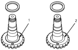
- 1. Number: A = +2
- 2. Number B = -1
| A: EXISTING TRANSFER | B: REPLACEMENT TRANSFER | |||||
| DRIVEN GEAR SHAFT | DRIVEN GEAR SHAFT | |||||
| A | B | |||||
| X = | - | + C | ||||
| 100 | 100 | |||||
| 2 | -1 | |||||
| = | - | + 1.05 | ||||
| 100 | 100 | |||||
| = | 0.02 + 0.01 + 1.05 | |||||
| = | 1.08 (mm) | |||||
Select 35 mm thrust shim thickness of 1.08 mm (0.043 in). If the tapered roller bearing on the transfer driven gear shaft is replaced.
Measure the thickness of the replacement bearing and the existing bearing thickness. Adjust the thickness of the existing 35 mm thrust shim by the amount of difference in bearing thickness and select the replacement 35 mm thrust shim.
THRUST SHIM, 35 mm
| Shim No. Part Number | Thickness | |
| A | 41361-PS3-000 | 0.72 mm (0.028 in) |
| B | 41362-PS3-000 | 0.75 mm (0.030 in) |
| C | 41363-PS3-000 | 0.78 mm (0.031 in) |
| D | 41364-PS3-000 | 0.81 mm (0.032 in) |
| E | 41365-PS3-000 | 0.84 mm (0.033 in) |
| F | 41366-PS3-000 | 0.87 mm (0.034 in) |
| G | 41367-PS3-000 | 0.90 mm (0.035 in) |
| H | 41368-PS3-000 | 0.93 mm (0.037 in) |
| I | 41369-PS3-000 | 0.96 mm (0.038 in) |
| J | 41370-PS3-000 | 0.99 mm (0.039 in) |
| K | 41371-PS3-000 | 1.02 mm (0.040 in) |
| L | 41372-PS3-000 | 1.05 mm (0.041 in) |
| M | 41373-PS3-000 | 1.08 mm (0.043 in) |
| N | 41374-PS3-000 | 1.11 mm (0.044 in) |
PDF p. 531 · 13-57
Transfer Gear Backlash Inspection and Transfer Gear Tooth Contact Inspection
- 2.
Install the 35 mm thrust shim on the transfer driven gear shaft, then install the tapered roller bearing using the special tools and a press as shown.
NOTE: Use old transfer spacer for bearing installation, then discard it.
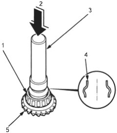
- 1. TAPERED ROLLER BEARING
- 2. PRESS
- 3. DRIVER, 40 mm I.D., 07746-0030100
- 4. OLD TRANSFER SPACER
- 5. TRANSFER DRIVEN GEAR SHAFT
- 3.Place the tapered roller bearing on the bearing outer race of the companion flange side of the transfer housing.
- 4.Install the new oil seal on the transfer housing using the special tools.
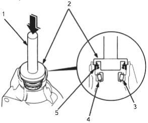
- 1. DRIVER, 07749-0010000
- 2. OIL SEAL DRIVER ATTACHMENT, 07JAD-PH80101
- 3. BEARING OUTER RACE
- 4. TAPERED ROLLER BEARING
- 5. OIL SEAL, Replace
- 5.Install the transfer driven gear shaft in the transfer housing. Do not install the transfer spacer on the transfer driven gear shaft in this step.
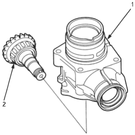
- 1. TRANSFER HOUSING
- 2. TRANSFER DRIVEN GEAR SHAFT
- 6.Install the companion flange, conical spring washer and locknut on the transfer driven gear shaft. Do not install the O-ring and the back-up ring on the transfer gear shaft in this step.
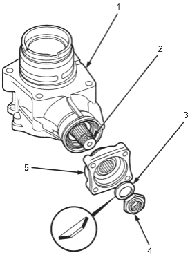
- 1. TRANSFER HOUSING
- 2. TRANSFER DRIVEN GEAR SHAFT
- 3. CONICAL SPRING WASHER, Install in this direction
- 4. LOCKNUT
- 5. COMPANION FLANGE
PDF p. 532 · 13-58
- 7.Secure the transfer housing in a bench vice with soft jaws, then install the special tool on the companion flange. To prevent damage to the transfer housing, always use soft jaws or equivalent materials between the transfer housing and the vice.
- 8.
Tighten the locknut while measuring the starting torque so the starting torque is within 0.98 - 1.39 Nm (10.0 - 14.2 kgf/cm, 8.68 - 12.3 lbf/in).
NOTE:
- Coat the threads of the locknut and the shaft with oil before installing the locknut.
- Do not stake the locknut at this step.
STARTING TORQUE:
0.98 - 1.39 Nm
(10.0 - 14.2 kgf/cm, 8.68 - 12.3 lbf/in)
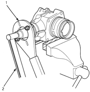
- 1. COMPANION FLANGE HOLDER, 07RAB-0020000
- 2. TORQUE WRENCH
- 9.
Install the transfer shaft assembly in the transfer housing, then install the tapered roller bearing, transfer shaft collar, 25 mm thrust shim, transfer drive gear, conical spring washer and locknut on the transfer shaft.
NOTE:
- Coat the threads of the locknut and the shaft with oil before installing the locknut.
- Do not stake the locknut at this step.
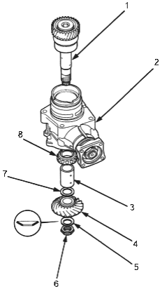
- 1. TRANSFER SHAFT ASSEMBLY
- 2. TRANSFER HOUSING
- 3. TRANSFER SHAFT COLLAR
- 4. TRANSFER DRIVE GEAR
- 5. CONICAL SPRING WASHER, Replace
- 6. LOCKNUT, Replace
- 7. THRUST SHIM, 25 mm, Selective part
- 8. TAPERED ROLLER BEARING
PDF p. 533 · 13-59
- 10.Put a 14 mm Allen wrench in the gear side of the transfer shaft, then secure the Allen wrench in a bench vice.
- 11.
Tighten the transfer shaft locknut.
NOTE:
- The transfer shaft locknut has left hand threads.
- Do not stake the locknut at this step.
TORQUE:
118 Nm (12.0 kgf/m, 86.8 lbf/ft)
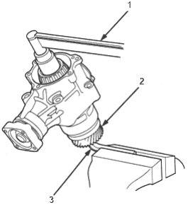
- 1. TORQUE WRENCH
- 2. TRANSFER SHAFT
- 3. 14 mm ALLEN WRENCH
- 12.Temporarily install the transfer cover A without the O-ring.
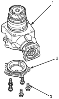
- 1. TRANSFER HOUSING
- 2. TRANSFER COVER A
- 3. 8 x 1.25 mm, 24 Nm (2.4 kgf/m, 17 lbf/ft)
- 13.Rotate the companion flange several times to seat the tapered roller bearing.
- 14.
Set a dial indicator on the companion flange, then measure the transfer gear backlash.
STANDARD: 0.06 - 0.16 mm (0.002 - 0.006 in)
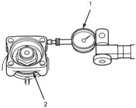
- 1. DIAL INDICATOR
- 2. COMPANION FLANGE
- 15.If the measurement is not within the standard, remove the transfer shaft locknut and replace the 25 mm thrust shim. Select and install a new 25 mm thrust shim, then recheck the measurement. Do not use more than one 25 mm thrust shim to adjust the transfer gear backlash.
THRUST SHIM, 25 mm
| Shim No. Part Number | Thickness | |
| 1 | 29411-P1C-000 | 1.70 mm (0.067 in) |
| 2 | 29412-P1C-000 | 1.73 mm (0.068 in) |
| 3 | 29413-P1C-000 | 1.76 mm (0.069 in) |
| 4 | 29414-P1C-000 | 1.79 mm (0.070 in) |
| 5 | 29415-P1C-000 | 1.82 mm (0.072 in) |
| 6 | 29416-P1C-000 | 1.85 mm (0.073 in) |
| 7 | 29417-P1C-000 | 1.88 mm (0.074 in) |
| 8 | 29418-P1C-000 | 1.91 mm (0.075 in) |
| 9 | 29419-P1C-000 | 1.94 mm (0.076 in) |
| 10 | 29420-P1C-000 | 1.97 mm (0.078 in) |
| 11 | 29421-P1C-000 | 2.00 mm (0.079 in) |
| 12 | 29422-P1C-000 | 2.03 mm (0.080 in) |
| 13 | 29423-P1C-000 | 2.06 mm (0.081 in) |
| 14 | 29424-P1C-000 | 2.09 mm (0.082 in) |
| 15 | 29425-P1C-000 | 2.12 mm (0.083 in) |
| 16 | 29426-P1C-000 | 2.15 mm (0.085 in) |
| 17 | 29427-P1C-000 | 2.18 mm (0.086 in) |
| 18 | 29428-P1C-000 | 2.21 mm (0.087 in) |
| 19 | 29429-P1C-000 | 2.24 mm (0.088 in) |
PDF p. 534 · 13-60
- 16.Apply Prussian Blue to both sides of the transfer gear teeth lightly and evenly.
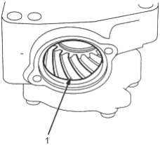
- 1. TRANSFER DRIVE GEAR
- 17.Rotate the companion flange in both directions until the transfer gear rotates one full turn in both directions.
- 18.Check the transfer gear tooth contact pattern.
CORRECT TOOTH CONTACT POSITION
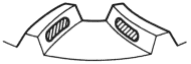
INCORRECT TOOTH CONTACT POSITION
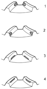
- 1. TOE CONTACT
- 2. HEEL CONTACT
- 3. FLANK CONTACT
- 4. FACE CONTACT
- 19.
If the transfer gear tooth contact is incorrect, adjust the transfer gear tooth contact with a 35 mm or 25 mm thrust shim.
NOTE:
- To select a 35 mm thrust shim, (See page 13-52).
- Do not use more than two 35 mm shim to adjust the transfer gear tooth contact.
- To select the 25 mm thrust shim (See page 13-55).
- Do not use more than one 25 mm shim to adjust the transfer gear tooth contact.
Toe Contact
Use a thicker 35 mm thrust shim to move the transfer driven gear shaft toward the transfer drive gear. Because this movement causes the transfer drive gear backlash to change, move the transfer drive gear away from the transfer driven gear shaft to adjust the transfer gear backlash as follows:
- Increase the thickness of the 25 mm thrust shim.
- Reduce the thickness of the 68 mm thrust shim by the amount of increased thickness of the 25 mm thrust shim.
Heel Contact
Use a thinner 35 mm thrust shim to move the transfer driven gear shaft away from the transfer drive gear. Because this movement causes the transfer gear backlash to change, move the transfer gear toward the transfer driven gear shaft to adjust the transfer gear backlash as follows:
- Reduce the thickness of the 25 mm thrust shim.
- Increase the thickness of the 68 mm thrust shim by the amount of reduced thickness of the 25 mm thrust shim.
Flank Contact
Use a thinner thrust shim to move the transfer drive gear toward the transfer driven gear shaft. Flank contact must be adjusted within limits of the transfer gear backlash. If the backlash exceeds the limits, adjust as described under Heel Contact.
Face Contact
Use a thicker thrust shim to move the transfer drive gear away from the transfer driven gear shaft. Face contact must be adjusted within limits of the transfer gear backlash. If the backlash exceeds the limits, adjust as described under Toe Contact.
PDF p. 535 · 13-61
- 20.Remove the parts on the transfer shaft and remove the transfer shaft from the transfer housing.
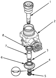
- 1. TRANSFER SHAFT
- 2. TRANSFER HOUSING
- 3. THRUST SHIM, 25 mm, Selective part
- 4. CONICAL SPRING WASHER, Replace
- 5. LOCKNUT, Replace
- 6. TRANSFER DRIVE GEAR
- 7. TRANSFER SHAFT COLLAR
- 8. TAPERED ROLLER BEARING
Transfer Driven Gear Shaft Starting Torque Inspection and Adjustment
- 21.Secure the transfer housing in a bench vice with soft jaws. To prevent damage, always use soft jaws or equivalent materials between the transfer housing and the vice.
- 22.Install the special tool on the companion flange, then remove the transfer driven gear shaft locknut and the conical spring washer.
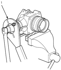
- 1. COMPANION FLANGE HOLDER, 07RAB-0020000
- 23.Remove the transfer driven gear shaft and the companion flange.
- 24.Install the new transfer spacer on the transfer driven gear shaft, then install them in the transfer housing.
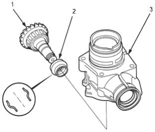
- 1. TRANSFER DRIVEN GEAR SHAFT
- 2. TRANSFER SPACER
Install in this direction, Replace - 3. TRANSFER HOUSING
- 25.
Install the companion flange, O-ring, back-up ring, conical spring washer and locknut on the transfer driven gear shaft.
NOTE:
- Coat the threads of the locknut and transfer shaft with oil before installing the locknut.
- Install the conical spring washer in the direction shown.
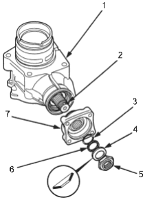
- 1. TRANSFER HOUSING
- 2. TRANSFER DRIVEN GEAR SHAFT
- 3. O-RING, Replace
- 4. CONICAL SPRING WASHER, Replace
- 5. LOCKNUT, Replace
- 6. BACK-UP RING
- 7. COMPANION FLANGE
PDF p. 536 · 13-62
- 26.Secure the transfer housing in a bench vice with soft jaws. To prevent damage, always use soft jaws or equivalent materials between the transfer housing and the vice.
- 27.
Install the special tool on the companion flange, then tighten the transfer driven gear shaft locknut while measuring the starting torque of the transfer driven gear shaft.
STARTING TORQUE:
0.98 - 1.39 Nm
(10.0 - 14.2 kgf/cm, 8.68 - 12.3 lbf/in)
TIGHTENING TORQUE
132 - 260 Nm
(13.5 - 26.5 kgf/m, 97.6 - 192 lbf/ft)
NOTE:
- Rotate the companion flange several times to seat the tapered roller bearing, then measure the starting torque.
- If the starting torque exceeds 1.39 Nm (14.2 kgf/cm, 12.3 lbf/in), replace the transfer spacer and reassemble the parts. Do not adjust the torque with the locknut loose.
- If the tightening torque exceeds 260 Nm (26.5 kg/fm, 192 lbf/ft), replace the transfer spacer and reassemble the parts.
- Write down the measurement of the starting torque; it is used to measure the total starting torque.
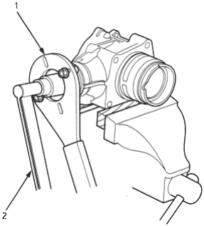
- 1. COMPANION FLANGE HOLDER, 07RAB-0020000
- 2. TORQUE WRENCH
- 28.Stake the locknut into the transfer driven gear shaft using a 3.5 mm punch as shown.
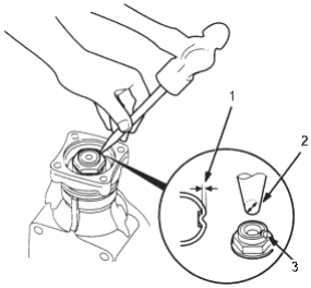
- 1. 0.7 - 1.2 mm (0.03 - 0.05 in)
- 2. PUNCH, 3.0 - 3.5 mm (0.12 - 0.14 in)
- 3. Point to be staked
- 29.
Install the transfer shaft assembly in the transfer housing, then install the tapered roller bearing, transfer shaft collar, 25 mm thrust shim, transfer drive gear, conical spring washer and transfer shaft locknut on the transfer shaft.
NOTE:
- Coat the threads of the locknut and transfer shaft with oil before installing the locknut.
- Install the conical spring washer in the direction shown.
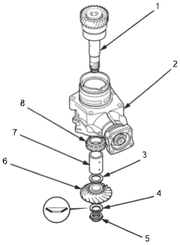
- 1. TRANSFER SHAFT ASSEMBLY
- 2. TRANSFER HOUSING
- 3. THRUST SHIM, 25 mm, Selective part
- 4. CONICAL SPRING WASHER, Replace
- 5. LOCKNUT, Replace
- 6. TRANSFER DRIVE GEAR
- 7. TRANSFER SHAFT COLLAR
- 8. TAPERED ROLLER BEARING
PDF p. 537 · 13-63
- 30.Put a 14 mm Allen wrench in the gear side of the transfer shaft, then secure the Allen wrench in a bench vice. Tighten the transfer shaft locknut. (The locknut has left hand threads.)
TORQUE: 118 Nm (12.0 kgf/m, 86.8 lbf/ft)
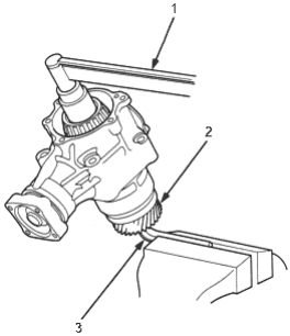
- 1. TORQUE WRENCH
- 2. TRANSFER SHAFT
- 3. 14 mm ALLEN WRENCH
- 31.Stake the locknut on the transfer shaft using a 3.5 mm punch.
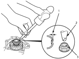
- 1. 0.7 - 1.2 mm (0.03 - 0.05 in)
- 2. PUNCH, 3.0 - 3.5 mm (0.12 - 0.14 in)
Total Starting Torque Inspection and Adjustment
- 32.Temporarily install transfer cover A without the O-ring.
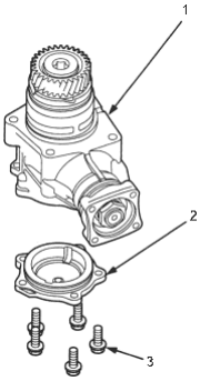
- 1. TRANSFER HOUSING
- 2. TRANSFER COVER A
- 3. 8 x 1.25 mm, 24 Nm (2.4 kgf/m, 17 lbf/ft)
- 33.Secure the transfer housing in a bench vice with soft jaws, then rotate the companion flange several times to fit the tapered roller bearing. To prevent damage, always use soft jaws or equivalent materials between the transfer housing and the vice.
- 34.Measure the total starting torque.
TOTAL STARTING TORQUE:
1.70 - 2.08 Nm (17.3 - 21.2 kgf/cm, 15.0 - 18.4 lbf/in) + Transfer Driven Gear Shaft Starting Torque Value (wrote down in step 27).
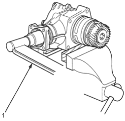
- 1. TORQUE WRENCH
PDF p. 538 · 13-64
- 35.Remove transfer cover A.
- 36.If the measurement is out of specification, remove the 68 mm thrust shim from transfer cover A by heating the cover to almost 212°F (100°C) using a heat gun. Do not heat the cover higher than 212°F (100°C). Let the cover cool to room temperature before adjusting the starting torque.
If the measurement is within the specification, go to step 40.
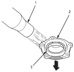
- 1. HEAT GUN
- 2. TRANSFER COVER A
- 3. BEARING OUTER RACE
- 37.Select the 68n mm thrust shim. THRUST SHIM, 68 mm
| Shim No. Part Number | Thickness | |
| ZV | 23974-P1C-020 | 1.41 mm (0.056 in) |
| ZW | 23975-P1C-020 | 1.44 mm (0.057 in) |
| ZX | 23976-P1C-020 | 1.47 mm (0.058 in) |
| ZY | 23977-P1C-020 | 1.50 mm (0.059 in) |
| ZZ | 23978-P1C-020 | 1.53 mm (0.060 in) |
| A | 23941-PW5-000 | 1.56 mm (0.061 in) |
| B | 23942-PW5-000 | 1.59 mm (0.063 in) |
| C | 23943-PW5-000 | 1.62 mm (0.064 in) |
| D | 23944-PW5-000 | 1.65 mm (0.065 in) |
| E | 23945-PW5-000 | 1.68 mm (0.066 in) |
| F | 23946-PW5-000 | 1.71 mm (0.067 in) |
| G | 23947-PW5-000 | 1.74 mm (0.069 in) |
| H | 23948-PW5-000 | 1.77 mm (0.070 in) |
| I | 23949-PW5-000 | 1.80 mm (0.071 in) |
| J | 23950-PW5-000 | 1.83 mm (0.072 in) |
| K | 23951-PW5-000 | 1.86 mm (0.073 in) |
| L | 23952-PW5-000 | 1.89 mm (0.074 in) |
| M | 23953-PW5-000 | 1.92 mm (0.076 in) |
| N | 23954-PW5-000 | 1.95 mm (0.077 in) |
| O | 23955-PW5-000 | 1.98 mm (0.078 in) |
| P | 23956-PW5-000 | 2.01 mm (0.079 in) |
| Q | 23957-PW5-000 | 2.04 mm (0.080 in) |
| R | 23958-PW5-000 | 2.07 mm (0.081 in) |
| S | 23959-PW5-000 | 2.10 mm (0.083 in) |
| T | 23960-PW5-000 | 2.13 mm (0.084 in) |
| U | 23961-PW5-000 | 2.16 mm (0.085 in) |
| V | 23962-PW5-000 | 2.19 mm (0.086 in) |
| W | 23963-PW5-000 | 2.22 mm (0.087 in) |
| X | 23964-PW5-000 | 2.25 mm (0.089 in) |
| Y | 23965-PW5-000 | 2.28 mm (0.090 in) |
| Z | 23966-PW5-000 | 2.31 mm (0.091 in) |
| AA | 23967-PW5-000 | 2.34 mm (0.092 in) |
| AB | 23968-PW5-000 | 2.37 mm (0.093 in) |
| AC | 23969-PW5-000 | 2.40 mm (0.094 in) |
| AD | 23970-PW5-000 | 2.43 mm (0.096 in) |
| AZ | 23971-PW8-000 | 2.46 mm (0.097 in) |
| BZ | 23972-PW8-000 | 2.49 mm (0.098 in) |
| CZ | 23973-PW8-000 | 2.52 mm (0.099 in) |
| DZ | 23974-PW8-000 | 2.55 mm (0.100 in) |
| EZ | 23975-PW8-000 | 2.58 mm (0.102 in) |
PDF p. 539 · 13-65
- 38.Install the 68 mm thrust shim using the special tools.
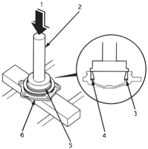
- 1. PRESS
- 2. DRIVER, 07749-0010000
- 3. THRUST SHIM, 68 mm, Selective part
- 4. BEARING OUTER RACE
- 5. ATTACHMENT, 62 x 68 mm, 07746-0010500
- 6. TRANSFER COVER A
- 39.After replacing the 68 mm thrust shim, recheck and make sure the total starting torque is within the specification.
- 40.Install the new O-rings on transfer covers A and B, then install the covers on the transfer housing.
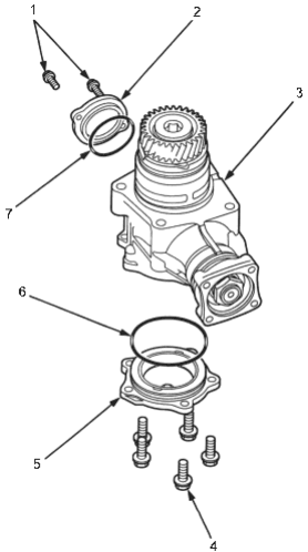
- 1. 6 x 1.0 mm, 12 Nm (1.2 kgf/m, 8.7 lbf/ft)
- 2. TRANSFER COVER B
- 3. TRANSFER HOUSING
- 4. 8 x 1.25 mm, 24 Nm (2.4 kgf/m, 17 lbf/ft)
- 5. TRANSFER COVER A
- 6. O-RING, Replace
- 7. O-RING, Replace