PDF p. 461 · 12-4
NOTE:
- To check the clutch switch, see section 23.
- The clutch is self adjusting to compensate for wear.
- 1.Loosen locknut A and back off the clutch switch (or adjusting bolt) until it no longer touches the clutch pedal.
- 2.Loosen locknut B, and turn the push rod in or out to get the specified stroke (A) and height (C) at the clutch pedal.
- 3.Tighten locknut B.
- 4.Turn the clutch switch (or adjusting bolt) in until it contacts the clutch pedal.
- 5.Turn the clutch switch (or adjusting bolt) in an additional 3/4 to 1 full turn.
- 6.Tighten locknut A
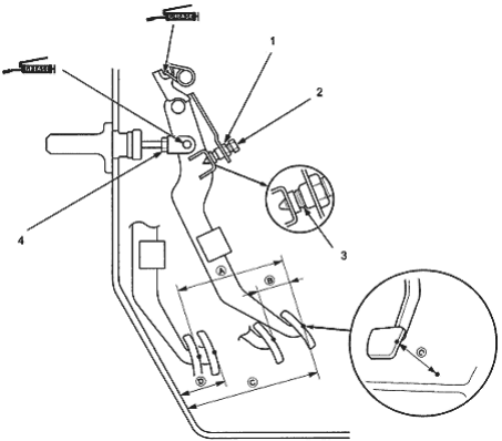
- 1. LOCKNUT A, 9.8 Nm (1.0 kgf/m, 7.2 lbf/ft)
- 2. ADJUSTING BOLT
- 3. PEDAL IN CONTACT WITH SWITCH
- 4. LOCKNUT B, 18 Nm (1.8 kgf/m, 13 lbf/ft)
| A | (STROKE at PEDAL): 130 - 140 mm (5.12 - 5.51 in) |
| B | (TOTAL CLUTCH PEDAL FREE PLAY): 8 - 18 mm (0.31 - 0.711 in) includes the pedal play 1.0 - 9.0 mm (0.04 - 0.35 in) |
| C | (CLUTCH PEDAL HEIGHT): LHD: 179 mm (7.05 in) to the floor |
RHD: 183 mm (7.2 in) to the floor
D (CLUTCH PEDAL DISENGAGEMENT HEIGHT) : LHD: 87 mm (3.43 in) minimum to the floor
RHD: 74 mm (2.91 in) minimum to the floor