PDF p. 1880 · 11-99
When the engine is cold, the A/C compressor is on, the transmission is in gear, the brake pedal is depressed, the P/S load is high, or the alternator is charging, the ECM/PCM controls current to the IAC valve to maintain the correct idle speed. Refer to the ECM/PCM Circuit Diagram to see the functional layout of the system.
Idle Air Control (IAC) Valve
To maintain the proper idle speed, the IAC valve changes the amount of air bypassing the throttle body in response to an electrical signal from the ECM/PCM.
D16W1 engine:
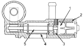
- 1. BIMETAL HOLDER
- 2. BIMETAL
- 3. STOPPER
- 4. VALVE
- 5. SHAFT
D16W5 engine:
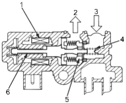
- 1. COIL
- 2. To INTAKE MANIFOLD
- 3. From AIR CLEANER
- 4. SPRING
- 5. VALVE
- 6. SHAFT
Power Steering Pressure Switch Signal
The P/S Pressure Switch signals the ECM/PCM when the power steering load is high.
Starter (Ignition) Switch
The starter switch signals the ECM/PCM when the engine is cranking.
Brake Switch
The brake switch signals the ECM/PCM when the brake pedal is depressed.