PDF p. 1931 · 11-152
Description
The evaporative emission controls are designed to minimise the amount of fuel vapour escaping to the atmosphere. The system consists of the following components:
- A.
Evaporative Emission (EVAP) Control Canister
An EVAP control canister is used for the temporary storage of fuel vapour until the fuel vapour can be purges from the EVAP control canister into the engine and burned.
- B.
Vapour Purge Control System
EVAP control canister purging is accomplished by drawing fresh air through the EVAP control canister and into a port on the throttle body. The purging vacuum is controlled by the EVAP purge control diaphragm valve and the EVAP purge control solenoid valve.
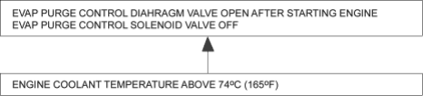
- C.
Fuel Tank Vapour Control System
When fuel vapour pressure in the fuel tank is higher than the set value of the EVA two way valve, the valve opens and regulates the flow of fuel vapour to the EVAP control canister.
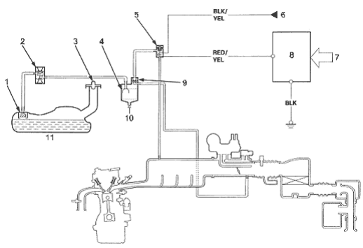
- 1. FUEL TANK EVAP VALVE
- 2. EVAP TWO WAY VALVE
- 3. FUEL FILL CAP
- 4. EVAP CONTROL CANISTER
- 5. EVAP PURGE CONTROL SOLENOID VALVE
- 6. INSTRUMENT LIGHT (7.5A) FUSE
- 7. VARIOUS SENSORS
- 8. PCM
- 9. EVAP PURGE CONTROL
DIAPHRAGM VALVE - 10. FRESH AIR
- 11. FUEL TANK