PDF p. 1920 · 11-141
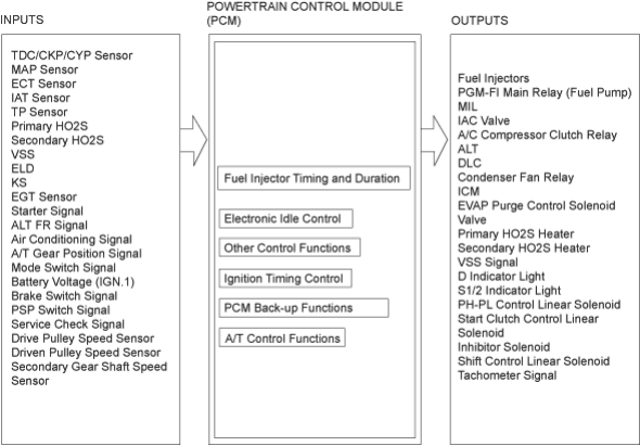
PGM-FI System
The PGM-FI system on this model is a sequential multiport fuel injection system.
Fuel Injector Timing and Duration
The PCM contains memories for the basic discharge durations at various engine speeds and manifold pressures. The basic discharge duration, after being read out from the memory, is further modified by signals sent from various sensors to obtain the final discharge duration.
Idle Air Control
When the engine is cold, the A/C compressor is on, the transmission is in gear, the brake pedal is depressed, the P/S load is high, or the alternator is charging, the PCM controls current to the IAC Valve to maintain the correct idle speed.
Ignition Timing Control
- The PCM contains memories for basic ignition timing at various engine speeds and manifold air flow rates. Ignition timing is also adjusted for engine coolant temperature.
PDF p. 1921 · 11-142
Other Control Functions
- 1.
Starting Control
When the engine is started, the PCM provides a rich mixture by increasing fuel injector duration.
- 2.Fuel Pump Control
- When the ignition switch is initially turned ON (II), the PCM supplies ground to the PGM-FI main relay that supplies current to the fuel pump for two seconds to pressurise the fuel system.
- When the engine is running, the PCM supplies ground to the PGM-FI main relay that supplies current to the fuel pump.
- When the engine is not running and the ignition is ON (II), the PCM cuts ground to the PGM-FI main relay which cuts current to the fuel pump.
- 3.Fuel Cut-off Control
- During Deceleration with the throttle valve closed, current to the fuel injectors is cut off to improve fuel economy at speeds over 1,100 rpm (min-1).
- Fuel cut-off action also takes place when the engine speed exceeds 7,000 rpm (min-1), regardless of the position of the throttle valve, to protect the engine from over-revving. With A/T model, when the vehicle stops, the PCM cuts the fuel at engine speeds over 5,000 rpm (min-1).
- 4.
A/C Compressor Clutch Relay
When the PCM receives a demand for cooling from the air conditioning system, it delays the compressor from being energised, and enriches the mixture to assure smooth transition to the A/C mode.
- 5.
Alternator Control
The system controls the voltage generated at the alternator in accordance with the electrical load and driving mode, which reduces the engine load to improve the fuel economy.
- 6.
Evaporative Emission (EVAP) Purge Control Solenoid Valve
When the engine coolant temperature is below 74°C (165°F), the PCM supplies a ground to the EVAP purge control solenoid valve which cuts vacuum to the EVAP purge control canister.
ECM/PCM Fail-safe/Back-up Functions
- 1.
Fail-safe Function
When an abnormality occurs in a signal from a sensor, the PCM ignores that signal and assumes a pre-programmed value for that sensor that allows the engine to continue to run.
- 2.
Back-up Function
When an abnormality occurs in the PCM itself, the fuel injectors are controlled by a back-up circuit independent of the system in order to permit minimal driving.
- 3.
Self-diagnosis Function [Malfunction Indicator Lamp (MIL)]
When an abnormality occurs in a signal from a sensor, the PCM supplies ground for the MIL and stores the code in erasable memory. When the ignition is initially turned ON (II), the PCM supplies ground for the MIL for two seconds to check the MIL bulb condition.