PDF p. 330 · 11-3
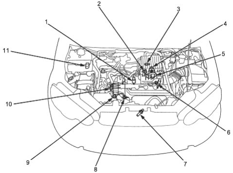
With TWC model:
- 1. EVAPORATIVE EMISSION (EVAP) PURGE CONTROL SOLENOID
VALVE (With TWC models) Troubleshooting, (See Page 11-108) - 2. THROTTLE POSITION (TP) SENSOR Troubleshooting, (See Page 11-41)
- 3. INTAKE AIR TEMPERATURE (IAT) SENSOR
Troubleshooting, (See Page 11-44) - 4. MANIFOLD ABSOLUTE PRESSURE (MAP) SENSOR
Troubleshooting, (See Page 11-34) - 5. IDLE AIR CONTROL (IAC) VALVE Troubleshooting, (See Page 11-63)
- 6. POWER STEERING PRESSURE (PSP) SWITCH
Troubleshooting, (See Page 11-71) - 7. PRIMARY HEATED OXYGEN
SENSOR (PRIMARY HO2S) (With TWC models)
Troubleshooting, (See Page 11-32) Replacement (See Page 11-60) - 8. ENGINE COOLANT TEMPERATURE (ECT) SENSOR
Troubleshooting , (See Page 11-39) - 9. VEHICLE SPEED SENSOR (VSS) Troubleshooting, (See Page 11-49)
- 10. TOP DEAD CENTRE/CRANKSHAFT POSITION/CYLINDER POSITION (CKP/TDC/CYP) SENSOR (Is built into the distributor)
Troubleshooting, (See Page 11-37) - 11. ELECTRICAL LOAD DETECTOR (ELD) (KG, KE, KQ, KU models) Troubleshooting, (See Page 11-51)
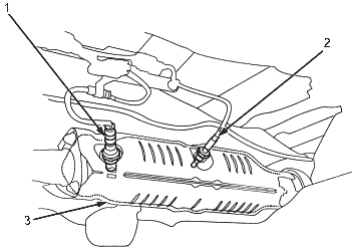
- 1. SECONDARY HEATED OXYGEN SENSOR (SECONDARY HO2S) (except KU model) Troubleshooting, (See Page 11-58) Replacement, (See Page 11-60)
- 2. EXHAUST GAS TEMPERATURE (EGT) SENSOR (except KU model) Troubleshooting, (See Page 11-56)
- 3. THREE WAY CATALYTIC CONVERTER (TWC)
Inspection, (See Page 11-104)
PDF p. 331 · 11-4
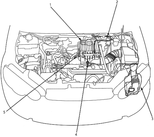
- 1. AIR CLEANER (ACL) Replacement, (See Page 11-99)
- 2. THROTTLE CABLE Inspection/Adjustment, (See Page 11-100)
Installation, (See Page 11-100) - 3. RESONATOR
- 4. POSITIVE CRANKCASE VENTILATION (PCV) VALVE Inspection, (See Page 11-105)
- 5. THROTTLE BODY (TB) Inspection(See Page 11-101) Disassembly, (See Page 11-102)
PDF p. 332 · 11-5
LHD:
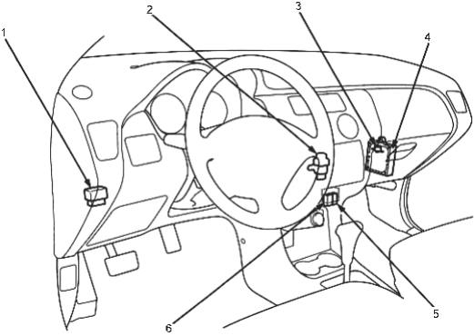
- 1. PGM-FI MAIN RELAY
Relay testing, (See Page 11-92) Troubleshooting, (See Page 11-93) - 2. INERTIA SWITCH
Description, (See Page 11-91) - 3. IDLE MIXTURE ADJUSTER (IMA) (Without TWC models) Troubleshooting, (See Page 11-46)
- 4. ENGINE CONTROL MODULE (ECM/POWERTRAIN CONTROL MODULE (PCM)
Removal, (See Page 11-15) Troubleshooting Procedures, (See Page 11-13)
Troubleshooting, (See Page 11-27) - 5. SERVICE CHECK CONNECTOR Self-diagnostic Procedures, (See Page 11-13)
- 6. DATA LINK CONNECTOR (DLC) (3P)
RHD:
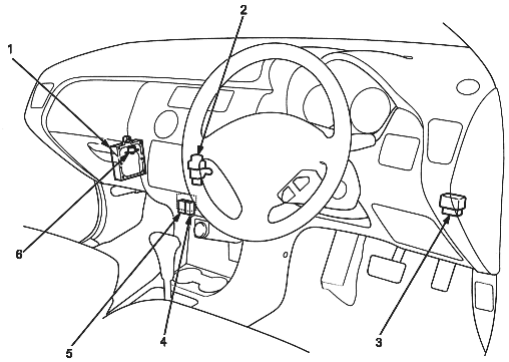
- 1. ENGINE CONTROL MODULE (ECM)/ POWERTRAIN CONTROL MODULE (PCM)
Removal, (See Page 11-15) Troubleshooting, Procedure, (See Page 11-13)
Troubleshooting, (See Page 11-27) - 2. INERTIA SWITCH
Description, (See Page 11-91) - 3. PGM-FI MAIN RELAY
Relay testing, (See Page 11-92) Troubleshooting, (See Page 11-93) - 4. DATA LINK CONNECTOR (DLC) (3P)
- 5. SERVICE CHECK CONNECTOR Self-diagnostic Procedures, (See Page 11-13)
- 6. IDLE MIXTURE ADJUSTER (IMA) (Without TWC models) Troubleshooting, (See Page 11-46)
PDF p. 333 · 11-6
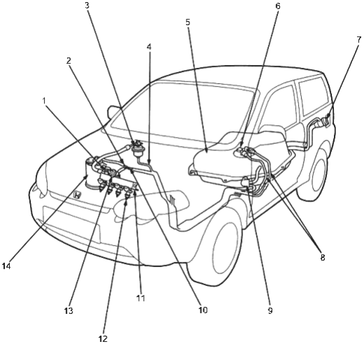
- 1.FUEL PULSATION DAMPER
- 2.FUEL VAPOUR PIPE
- 3.
FUEL FILTER
Replacement (See Page 11-86)
- 4.FUEL FEED PIPE
- 5.
FUEL TANK
Replacement (See Page 11-96)
- 6.
FUEL PUMP
Testing (See Page 11-87) Replacement (See Page 11-87)
FUEL GAUGE SENDING UNIT
Testing (See Page 11-89)
- 7.FUEL FILL CAP
- 8.
FUEL TUBE/QUICK-CONNECT FITTINGS
Precautions (See Page 11-77) Disconnection, (See Page 11-77) Connection (See Page 11-78)
- 9.
EVAPORATIVE EMISSION (EVAP) TWO WAY VALVE
Testing (See Page 11-111)
- 10.FUEL RETURN PIPE
- 11.FUEL RAIL
- 12.
FUEL INJECTORS
Testing (See Page 11-82) Replacement (See Page 11-83)
- 13.
FUEL PRESSURE REGULATOR
Testing (See Page 11-85) Replacement, (See Page 11-86)
14 EVAPORATIVE EMISSION (EVAP)
CONTROL CANISTER
Troubleshooting, (See Page 11-108) Testing, (See Page 11-110)