PDF p. 262 · 6-23
NOTE: Identify valves and valve springs as they are removed so that each item can be reinstalled in its original position.
- 1.Using an appropriate-sized socket and plastic mallet, lightly tap the valve retainer to loosen the valve keepers before installing the valve spring compressor.
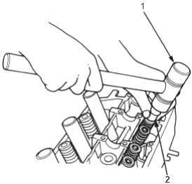
- 1. PLASTIC MALLET
- 2. SOCKET
- 2.Install the spring compressor. Compress the spring and remove the valve keeper.
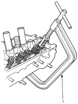
- 1. VALVE SPRING COMPRESSOR, 07757-0010000
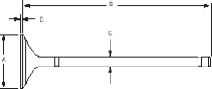
Intake Valve Dimensions
| A Standard (New): | 29.90 - 30.10 mm) |
| (1.177 - 1.185 in) | |
| B Standard (New): | 117.42 - 117.72 mm |
| (4.623 - 4.635 in) | |
| C Standard (New): | 5.48 - 5.49 mm |
| (0.2157 - 0.2161 in) | |
| C Service Limit: | 5.45 mm (0.2146 in) |
| D Standard (New): | 0.85 - 1.15 mm |
| (0.033 - 0.045 in) | |
| D Service Limit: | 0.55 mm (0.022 in) |
| Exhaust Valve Dimensions | |
| A Standard (New): | 25.90 - 26.10 mm |
| (1.020 - 1.028 in) | |
| B Standard (New): | 114.60 - 114.90 mm |
| (4.512 - 4.524 in) | |
| C Standard (New): | 5.45 - 5.46 mm |
| (0.2146 - 0.2150 in) | |
| C Service Limit: | 5.42 mm (0.2134 in) |
| D Standard (New): | 1.05 - 1.35 mm |
| (0.041 - 0.053 in) | |
| D Service Limit: | 0.85 mm (0.033 in) |