PDF p. 242 · 6-3
NOTE:
- Valves should be adjusted only when the cylinder head temperature is less than 38°C (100°F).
- After adjusting, loosen the crankshaft pulley bolt, then retorque the crankshaft pulley bolt to 20 Nm (2.0 kgf/m, 14 lbf/ft) + 90°
- 1.Remove the breather hose, then remove the air cleaner housing (see page 5-4).
- 2.
Remove the cylinder head cover.
NOTE: When installing the cylinder head cover (see page 6-30).
- 3.Remove the upper cover (see page 6-9).
- 4.Set the No. 1 piston at TDC. “UP” mark on the camshaft pulley should be at top, and TDC marks should align with the cylinder head upper surface.
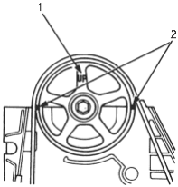
- 1. “UP” MARK
- 2. TDC MARKS
- 5.
Adjust valves on No.1 cylinder.
Intake: 0.20 mm (0.008 in) + 0.02 mm (0.008 in) Exhaust: 0.25 mm (0.010 in) + 0.02 mm (0.008 in)
- 6.
Loosen locknut and turn adjustment screw until feeler gauge slides back and forth with slight amount of drag.
NOTE: Do not overtighten the locknuts, for the rocker arms are made of aluminium.
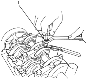
- 1. INTAKE and EXHAUST VALVE LOCKNUTS 18 Nm (1.8 kgf/m, 13 lbf/ft)
Adjusting screw location:
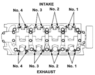
- 1.No.1
- 2.No.2
- 3.No.3
- 4.No.4
- 5.No.5
- 6.No.6
- 7.No.7
- 8.No.8
PDF p. 243 · 6-4
- 7.Tighten the locknut, and check clearance again. Repeat the adjustment if necessary.
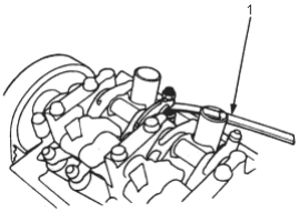
- 1. FEELER GAUGE
- 8.
Rotate the crankshaft 180° counterclockwise (camshaft pulley turns 90°). The “UP” mark should be on the exhaust side.
Adjust valves on No. 3 cylinder.
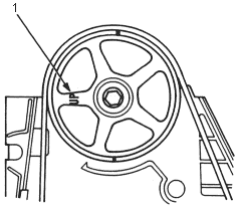
- 1. “UP” MARK
- 9.Rotate the crankshaft 180° counterclockwise to bring No. 4 piston to TDC. Both TDC grooves are once again visible. Adjust valves on No. 4 cylinder.
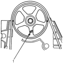
- 1. “UP” MARK
- 10.
Rotate the crankshaft 180° counterclockwise to bring No. 2 piston to TDC. The “UP” mark should be on the intake side.
Adjust valves on No. 2 cylinder.
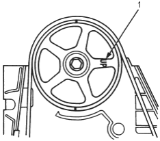
- 1. “UP” MARK