PDF p. 227 · 5-3
NOTE:
- Use fender covers to avoid damaging painted surfaces.
- To avoid damage, unplug the wiring connectors carefully while holding the connector portion.
- Mark all wiring and hoses to avoid misconnection. Also, be sure that they do not contact other wiring or hoses, or interfere with other parts.
- 1.Secure the hood in the open position as possible.
- 2.Disconnect the battery negative terminal first, then the positive terminal.
- 3.Remove the battery cables from the under-hood fuse/relay box.
- 4.Remove the harness clamp.
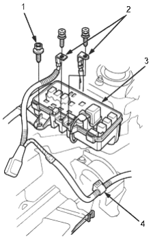
- 1. 6 x 1.0 mm, 9.8 Nm (1.0 kgf/m, 7.2 lbf/ft)
- 2. BATTERY CABLES
- 3. UNDER-HOOD FUSE/RELAY BOX
- 4. HARNESS CLAMP
- 5.Disconnect the engine wire harness connector on the right side of the engine compartment.
- 6.Remove the harness clamps.
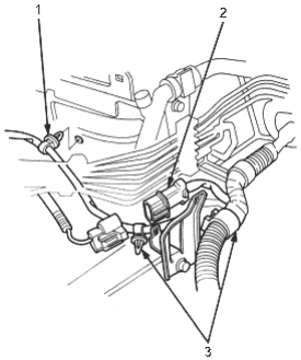
- 1. HARNESS CLAMP
- 2. ENGINE WIRE HARNESS CONNECTOR
- 3. HARNESS CLAMPS
- 7.Remove the intake air duct B.
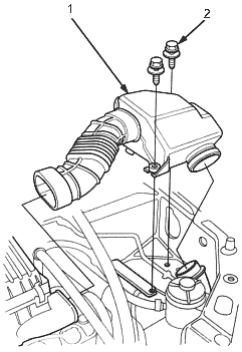
- 1. INTAKE AIR DUCT B
- 2. 6 x 1.0 mm, 9.8 Nm (1.0 kgf/m, 7.2 lbf/ft)
PDF p. 228 · 5-4
- 8.Remove the breather hose, then disconnect the intake air temperature (IAT) sensor connector.
- 9.Remove the air cleaner housing and the intake air duct.
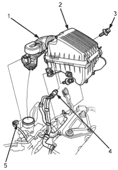
- 1. INTAKE AIR DUCT
- 2. AIR CLEANER HOUSING
- 3. 6 x 1.0 mm, 9.8 Nm (1.0 kgf/m, 7.2 lbf/ft)
- 4. BREATHER HOSE
- 5. IAT SENSOR CONNECTOR
- 10.Remove the mounting bolt and lock bolt, then remove the power steering (P/S) pump belt and pump without disconnecting the P/S hoses.
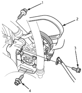
- 1. MOUNTING BOLT, 8 x 1.25 mm, 24 Nm (2.4 kgf/m, 17 lbf/ft)
- 2. P/S PUMP BELT
- 3. 6 x 1.0 mm, 9.8 Nm (1.0 kgf/m, 7.2 lbf/ft)
- 4. LOCK BOLT, 8 x 1.25 mm, 24 Nm (2.4 kgf/m, 17 lbf/ft)
- 11.Remove the P/S pump bracket.
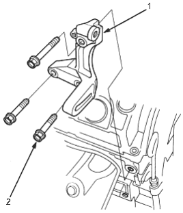
- 1. P/S PUMP BRACKET
- 2. 10 x 1.25 mm, 44 Nm (4.5 kgf/m, 33 lbf/ft)
- 12.Loosen the idler pulley centre nut adjusting bolt, then remove the air conditioning (A/C) compressor belt.
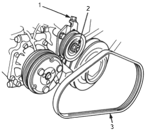
- 1. ADJUSTING BOLT
- 2. IDLER PULLEY CENTRE NUT 10 x 1.25 mm, 44 Nm (4.5 kgf/m, 33 lbf/ft)
- 3. A/C COMPRESSOR BELT
PDF p. 229 · 5-5
- 13.Remove the A/C compressor without disconnecting the A/C hoses.
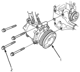
- 1. A/C COMPRESSOR
- 2. 8 x 1.25 mm, 24 Nm (2.4 kgf/m, 17 lbf/ft)
- 14.
Remove the throttle cable by loosening the locknut, then slip the cable end out of the accelerator linkage.
NOTE:
- Take care not to bend the cable when removing it. Always replace any kinked cable with a new one.
- Adjust the throttle cable when installing (see section 11).
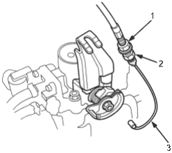
- 1. LOCKNUT
- 2. ADJUSTING NUT
- 3. THROTTLE CABLE
- 15.Relieve fuel pressure (see section 11).
- 16.Remove the fuel feed hose, fuel return hose and evaporative emission (EVAP) control canister hose.
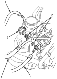
- 1. EVAP CONTROL CANISTER HOSE
- 2. WASHERS, Replace
- 3. FUEL RETURN HOSE
- 4. FUEL FEED HOSE
- 5. 33 Nm (3.4 kgf/m, 25 lbf/ft)
- 17.Remove the brake booster vacuum hose and vacuum hose.
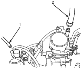
- 1. VACUUM HOSE
- 2. BRAKE BOOSTER VACUUM HOSE
PDF p. 230 · 5-6
- 18.Disconnect the engine control module (ECM)/ powertrain control module (PCM) connectors from the ECM/PCM, then disconnect the engine wire harness connectors.
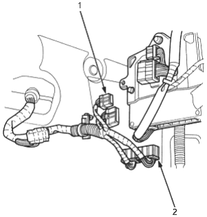
- 1. ENGINE WIRE HARNESS CONNECTORS
- 2. ECM/PCM CONNECTORS.
- 19.Remove the harness clamp and grommet, then pull out the ECM/PCM connectors.
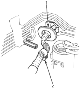
- 1. GROMMET
- 2. HARNESS CLAMP
- 20.Remove the shift cable. Take care not to bend the cable when removing them. Always replace any kinked cable with a new one (CVT).
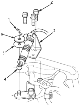
- 1. SPRING PIN
- 2. 8 x 1.25 mm, 26 Nm (2.7 kgf/m, 20 lbf/ft)
- 3. SHIFT CABLE HOLDER
- 4. SHIFT CABLE
- 5. PLASTIC WASHER
- 6. STEEL WASHER
- 21.Remove the shift cable and select cable. Take care not to bend the cables when removing them. Always replace any kinked cable with a new one (M/T).
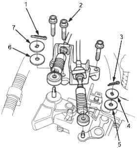
- 1. COTTER PIN. Replace
- 2. 8 x 1.25 mm, 27 Nm (2.8 kgf/m, 21 lbf/ft)
- 3. COTTER PIN, Replace
- 4. STEEL WASHER
- 5. PLASTIC WASHER
- 6. PLASTIC WASHER
- 7. STEEL WASHER
PDF p. 231 · 5-7
- 22.
Remove the clutch slave cylinder and line/hose assembly (M/T).
NOTE:
- Do not disconnect the line/hose assembly.
- Do not operate the clutch pedal once the slave cylinder has been removed.
- Take care not to bend the line.
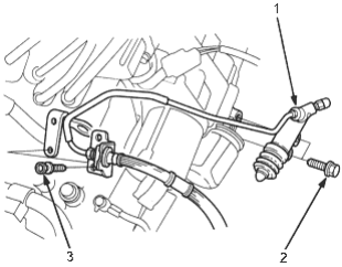
- 1. SLAVE CYLINDER
- 2. 8 x 1.25 mm, 22 Nm (2.2 kgf/m, 16 lbf/ft)
- 3. 6 x 1.0 mm, 9.8 Nm (1.0 kgf/m, 7.2 lbf/ft)
- 23.Remove the radiator cap.
- 24.Raise the hoist to full height.
- 25.Remove the front tires/wheels.
- 26.Remove the splash shield.
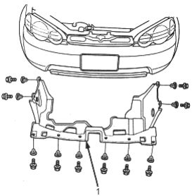
- 1. SPLASH SHIELD
- 27.Loosen the drain plug in the radiator, drain the engine coolant (See Page 10-5).
- 28.Drain the transmission oil or fluid. Reinstall the drain plug using a new washer (see section 13 (M/T) or section 14 (CVT).
- 29.Drain the engine oil. Reinstall the drain bolt using a new washer (See Page 8-5).
- 30.Disconnect the stabiliser links (see section 18).
- 31.Disconnect the suspension lower arm ball joints (see section 18).
- 32.
Remove the driveshafts (see section 16).
NOTE: Coat all precision finished with clean engine oil. Tie plastic bags over the driveshaft ends.
PDF p. 232 · 5-8
- 33.Remove exhaust pipe A.
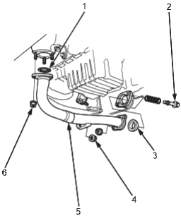
- 1. GASKET, Replace
- 2. 8 x 1.25 mm, 22 Nm (2.2 kgf/m, 16 lbf/ft). Replace
- 3. GASKET, Replace
- 4. SELF-LOCKING NUT 8 x 1.25 mm, 16 Nm (1.6 kgf/m, 12 lbf/ft), Replace
- 5. EXHAUST PIPE A
- 6. SELF-LOCKING NUT 10 x 1.25 mm, 54 Nm (5.4 kgf/m, 40 lbf/ft), Replace
- 34.Lower the hoist, then remove the upper radiator hose, lower radiator hose and the heater hoses.
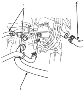
- 1. HEATER HOSES
- 2. UPPER RADIATOR HOSE
- 3. LOWER RADIATOR HOSE
- 35.Remove the hose clamp and ground cable.
- 36.Remove the ATF cooler hoses, then plug the ATF cooler hoses and lines.
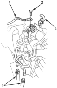
- 1. GROUND CABLE
- 2. 6 x 1.0 mm, 9.8 Nm (1.0 kgf/m, 7.2 lbf/ft)
- 3. HOSE CLAMP
- 4. ATF COOLER HOSES
PDF p. 233 · 5-9
- 37.Attach the chain hoist to the engine as shown.
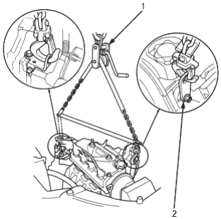
- 1. ENGINE TILT HANGER SET, 07KAK-SJ40101 (Except EU)
- 2. ENGINE SUB HANGER STAY, 07MAK-PY30100 (Except EU)
- 38.Raise the hoist to full height.
- 39.Remove the rear beam.
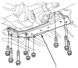
- 1. REAR BEAM
- 40.Remove the shift cable bracket from the rear mount bracket (CVT).
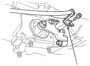
- 1. SHIFT CABLE BRACKET
- 41.When removing the propeller shaft, marks on the transfer companion flange and propeller shaft as shown. Use these marks to set the propeller shaft in the proper position when reinstalling.
- 42.Remove the four bolts securing the propeller shaft, then separate the propeller shaft from the transfer companion flange.
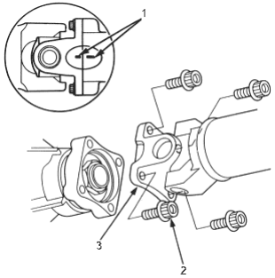
- 1. MARK
- 2. 8 x 1.25 mm, 32 Nm (3.3 kgf/m, 24 lbf/ft)
- 3. PROPELLER SHAFT
PDF p. 234 · 5-10
- 43.Remove the left front mount bracket mounting bolts.
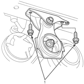
- 1. MOUNTING BOLTS
- 44.Remove the right front mount mounting bolts.
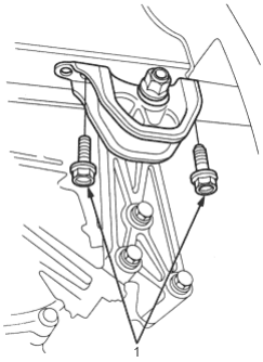
- 1. MOUNTING BOLTS
- 45.Remove the side engine mount support nuts.
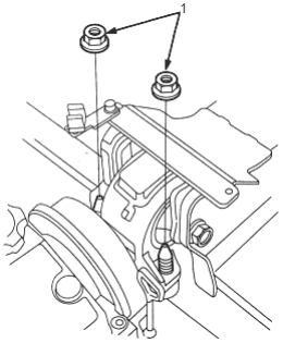
- 1. SUPPORT BOLTS
- 46.Remove the transmission mount bracket support bolt/nuts.
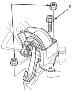
- 1. SUPPORT NUTS
- 2. SUPPORT BOLT
- 47.Check that the engine/transmission is completely free of vacuum hoses, fuel and coolant hoses, and electrical wiring.
- 48.Slowly lower the engine approximately 150 mm (6 in.). Check once again all hoses and wiring are disconnected from the engine.
- 49.Lower the engine all the way. Remove the chain hoist from the engine.
- 50.Remove the engine from under the vehicle.