How to Use This Manual
This supplement contains information for the 2000 HONDA HR-V. Refer to following shop manual for service procedures and data not included in this supplement.
| Description | Code No. |
| HONDA HR-V MAINTENANCE, | 62S2H00 |
REPAIR and CONSTRUCTION 99
Each section includes:
- 1.A table of contents, or an exploded view index showing:
- Parts disassembly sequence.
- Bolt torques and thread sizes.
- Page references to descriptions in text.
- 2.Disassembly/assembly procedures and tools.
- 3.Inspection.
- 4.Testing/troubleshooting.
- 5.Repair.
- 6.Adjustments.
Special Information
⚠ WARNING : Indicates a strong possibility of severe personal injury or loss of life if instructions are not followed.
⚠ CAUTION : Indicates a possibility of personal injury or equipment damage if instructions are not followed.
NOTICE : The purpose of these messages is intended to help prevent damage to the vehicle, other property, or the environment.
NOTE: Gives helpful information.
All information contained in this manual is based on the latest product information available at the time of printing. We reserve the right to make changes at any time without notice. No part of this publication may be reproduced, stored in retrieval system, or transmitted, in any form by any means, electronic, mechanical, photocopying, recording, or otherwise, without the prior written permission of the publisher. This includes text, figures and tables.
Greyed out sections are not included in this manual.
| First Edition 8/99 | 376 pages | HONDA MOTOR CO., LTD. |
| All Rights Reserved | Service Publication Office | |
As sections with * include SRS components;
special precautions are required when servicing.
SUPPLEMENTAL RESTRAINT SYSTEM (SRS)
This model has an SRS which includes a driver’s airbag located in the steering wheel hub and a passenger’s airbag located in the dashboard above the glove box and seat belt tensioners located in the seat belt retractors.
Information necessary to safely service the SRS is included in the Shop Manual, P/N 62S2H00.
Items marked with an asterisk (*) on the contents page include, or are located near, SRS components. Servicing, disassembling or replacing these items will require special precautions and tools, and should therefore be done by an authorised Honda dealer.
- General Info

- Specifications

- Maintenance

- Engine Electrical

- Engine

- Cooling

- Fuel & Emissions

- * Transaxle

- * Steering

- Suspension

- * Brakes (including ABS)

- * Body

- *Heating & Air Conditioning

- * Body Electrical

- * Restraints

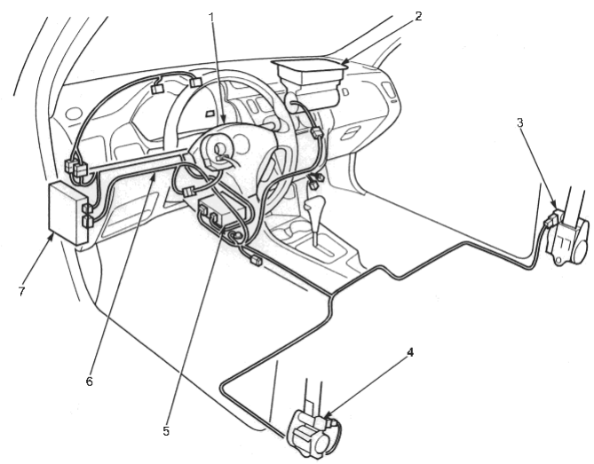
- 1. DRIVER’S AIRBAG ASSEMBLY
- 2. FRONT PASSENGER’S AIRBAG ASSEMBLY
- 3. FRONT PASSENGER’S SEAT BELT RETRACTOR (With tensioner)
- 4. DRIVER’S SEAT BELT RETRACTOR (With tensioner)
- 5. SRS UNIT (With built- in sensor)
- 6. SRS MAIN HARNESS (Indicated by yellow color coding)
- 7. UNDER- DASH FUSE/RELAY BOX
| ITEM | DESCRIPTION | 00 | REFERENCE | ||
|---|---|---|---|---|---|
| MODEL | SECTION | ||||
| General | 5-door model added | O | 1 | ||
| Engine | D16W5 engine added for KG, KE, KQ and KU models | O | 6, 9, 10 | ||
| Fuel and Emission | For KE and KG models: | ||||
| ♦ | D16W5 engine has been added and changed the following: | ||||
| - | Vacuum Connections | ||||
| - | Electrical Connections | ||||
| - | The knock Sensor has been added | ||||
| - | Idle Speed Setting | ||||
| - | Fuel Pressure Relieving/Inspection | ||||
| - | Fuel Filter | ||||
| - | Throttle Body | ||||
| - | Fuel Injector Air Control System | O | 11 | ||
| ♦ | The ECM/PCM has been changed | ||||
| ♦ | The EVAP control canister has been changed | ||||
| ♦ | The EVAP Two Way valve has been changed | ||||
| For KQ and KU models: | |||||
| ♦ | D16W5 engine has been added and changed the following: | ||||
| - | Vacuum Connections | ||||
| - | Electrical Connections | ||||
| - | The knock Sensor has been added | ||||
| - | Idle Speed Setting | ||||
| - | Fuel Pressure Relieving/Inspection | ||||
| - | Fuel Filter | ||||
| - | Throttle Body | ||||
| Automatic | For KE and KG models: | ||||
| Transmission | ♦ | Electrical troubleshooting procedures changed | O | 14 | |
| ♦ | Electrical system symptom-to-component chart modified | ||||
| For KQ and KU models: | |||||
| ♦ | S1 and S2 mode position driving system added | ||||
| Body | ♦ | 5-door model added | O | 20 | |
| ♦ | Roof spoiler with a built-in high mount brake light adopted | ||||
| Body Electrical | ♦ | Some electrical circuits changed | |||
| ♦ | Power window master switch with light (LED) adopted | ||||
| ♦ | A/T gear position console light added | ||||
| ♦ | LED type high mount brake light added available as an option | O | 23 | ||
| For KE and KG models: | |||||
| ♦ | Rear fog light switch and headlight adjuster switch changed | ||||
| ♦ | Hazard warning light removed | ||||
| For KG model: | |||||
| Seat heater switch changed | |||||
| Restraints | Seat Belts | O | 24 | ||
| Seat belts replacement procedure on 5-door model added | |||||
| Supplemental Restraint System (SRS) | |||||
| Front seat belt replacement on 5-door model added | |||||